| C H A P T E R 4 |
|
Network Planning |
This section provides recommended network configurations and worksheets for planning system and domain setups.
The Sun Fire E25K/E20K systems require 10BASE-T or 100BASE-TX Ethernet connections for each System Control (SC) board.
There are several networks to plan and set up for Sun Fire E25K/E20K systems. Two networks are internal to the platform, the others are external and require cabling. The networks are defined in TABLE 4-1.
The information in the sections below must be determined prior to the installation of Sun Fire E25K/E20K systems. Most system information is network related and must be provided by the customer. TABLE 4-2 identifies the network interfaces available and their function.
|
Connection to the internal network I1 from the master SC. There is only one address assigned for the pair of SCs. Only the master SC accesses the I1 network. |
|
|
Pathgroup specific failover address for each Cx pathgroup. PCx interfaces remain local to the SC[1]. |
|
|
Logical interface for each C network on the SC. The interface is reachable through the appropriate Cx network. F-Cx interfaces are only present on the main SC. |
|
All external connections to the SC should be through the user community logical interface L-Cx, so clients are always directed to the main SC.
For the System Controller, there are two types of network configurations: high availability (HA) and non HA. In either of the network configurations, the following is true:
|
Note - The cPCI slot in the SC is not currently supported and is not available for network connections. |
Network configurations for the domains are not discussed and are left to the specific requirements of the customer and application.
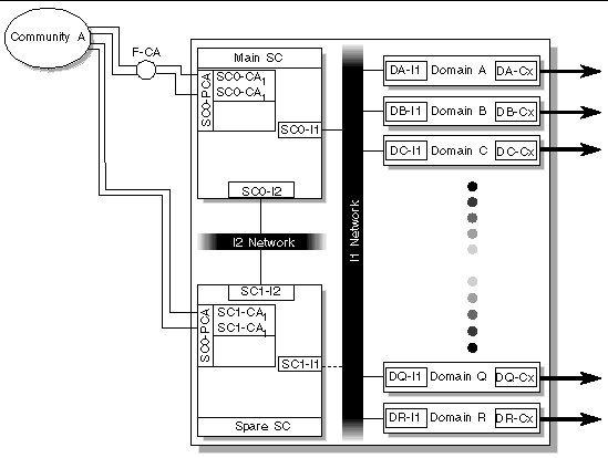
HA network configuration is shown in FIGURE 4-1.

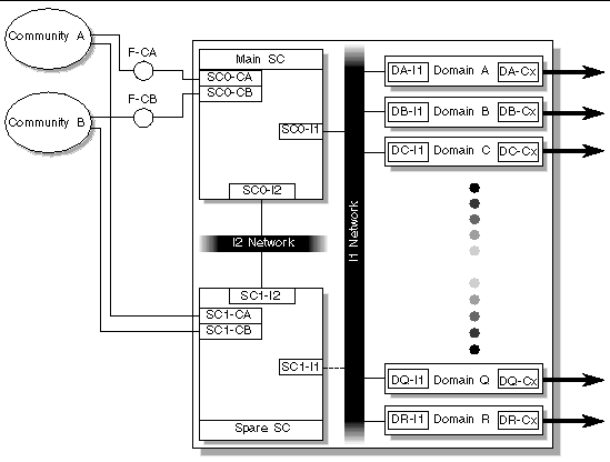
A non-HA network configuration is shown in FIGURE 4-2.

Host names, networks, internet protocol (IP) addresses, and subnet masks for the System Controllers are required. Domain OS installation also requires host names, IP addresses, and subnet masks for the domain external connections. Multiple user communities may also be involved. The worksheets that follow are designed to help organize this information before the installation.
Sun Fire E25K/E20K systems require a platform name. The platform name, globally unique within the network, is a logical name given to an entire system and does not correspond to any host on the network. The platform name is used as the default prefix for host names of internal network interfaces, see Section 4.4.2, Internal Networks. This platform name must consist of alphanumeric characters using an alpha character first. Record the platform name in the space provided in TABLE 4-3 (see Appendix A for an expanded form to use and retain for your records).
Enter the IP networks and subnet masks in the worksheet provided in TABLE 4-4 (see Appendix A for an expanded form to use and retain for your records). The subnets for the internal networks are fixed. As neither I1 nor I2 are routed, the IP networks can be taken from the IP private pool. Networks should be unique within the customer network.
Host names and IP addresses are required for the I1 network. For the System Controller, only one host name and IP address is assigned to the I1 network. Only the main SC actively connects to the I1 network.
The host names and IP addresses can be automatically assigned by smsconfig(1M) during installation. For example, if the platform name is Name1, domain A I1 host name becomes Name1-a. IP assignments are made based on the IP network subnet mask provided from lowest to highest starting with the SC and ending with domain R.
|
Note - Automatic assignment of a host name IP address for the I1 network is highly recommended. |
If performing a manual installation, record the host names and IP addresses for the I1 interfaces in the worksheet provided in TABLE 4-5.
Each System Controller maintains an active link to the I2 network, regardless of the SC role (main or spare). As with the I1 network, the I2 host name names and IP addresses can be automatically assigned during installation by smsconfig(1M).
|
Note - Automatic assignment of a host name IP address for the I2 network is highly recommended. |
If performing a manual installation, record the host names and IP addresses for the I2 interfaces in the worksheet provided in TABLE 4-6.
Enter the IP networks and subnet masks in the worksheet provided in TABLE 4-7. Each subnet must be unique within the network. The System Controller can connect to a maximum of two user communities.
IP addresses are required for every interface on the System Controller that is cabled to a user community. The SC has two built-in Ethernet ports (labeled "Ethernet" and "Ext Ethernet"). Use the worksheet in TABLE 4-8 to record this information.
Additionally, for each user community, a logical interface is required for the System Controllers. Logical interfaces are only present on the main SC. SC pathgroup-specific IP addresses are also required when using the HA configuration. Use the worksheet in TABLE 4-9 to record this information.
|
Note - The logical and pathgroup-specific IP address for a community must use the same IP network and subnet as the physical NIC(s) in that community. |
Host names and IP addresses are also required for the domain connections to a user community. The worksheet in TABLE 4-10 assumes that each domain connects to only one user community. If a domain connects to multiple user communities, or user communities not previously defined, record that information on a separate sheet of paper.
Copyright © 2007, Sun Microsystems, Inc. All Rights Reserved.