| Sun SPARC Enterprise T2000 Server Installation Guide
|
   
|
Preparing for Installation
|
This chapter provides background information about the server installation procedures that are provided in Chapter 2.
This chapter contains these topics:
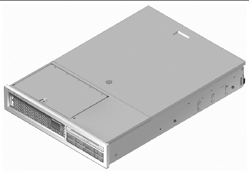
FIGURE 1-1 SPARC Enterprise T2000 Server
Tools and Equipment Needed
In order to install the system, you must have the following tools:
- #2 Phillips screwdriver
- ESD mat and grounding strap
In addition, you must provide a system console device, such as one of the following:
- ASCII terminal
- Sun workstation
- Terminal server
- Patch panel connected to a terminal server
Optional Component Installation
The standard components of the server are installed at the factory. However, if you ordered options such as additional memory or a PCI card, these will be shipped separately. If possible, install these components prior to installing the server in a rack.
If you ordered any options that are not factory-installed, see the Sun SPARC Enterprise T2000 Server Service Manual for installation instructions.
|
Note - The list of optional components can be updated without notice. See the web site for the most current list of components supported in the server.
|
ESD Precautions
Electronic equipment is susceptible to damage by static electricity. Use a grounded antistatic wriststrap, footstrap, or equivalent safety equipment to prevent electrostatic damage (ESD) when you install or service the server.

|
Caution - To protect electronic components from electrostatic damage, which can permanently disable the system or require repair by Sun service technicians, place components on an antistatic surface, such as an antistatic discharge mat, an antistatic bag, or a disposable antistatic mat. Wear an antistatic grounding strap connected to a metal surface on the chassis when you work on system components.
|
Installation Overview
This installation guide provides procedures which are to be performed in the following order.
1. Verify that you have received all of the components that ship with your server. See Shipping Kit Inventory List.
2. Gather configuration information for your system. See your system administrator for specific details, including these parameters:
- Netmask
- IP address for the system controller
- Gateway IP address
3. Install any optional Sun components shipped with your system. If you have purchased other optional components such as additional memory, install them prior to mounting the server in a rack. See Optional Component Installation.
4. Mount the server into a rack or cabinet. See Installing the Server in a Rack.
|
Note - In the rest of this manual, the term rack means either an open rack or a closed cabinet.
|
5. Connect the server to a serial terminal or a terminal emulator (PC or workstation) to display system messages. See Powering On the System for the First Time.
|
Tip - The serial terminal or a terminal emulator should be connected before you connect the power cables. As soon as AC power is connected to the system, the system controller immediately powers on and runs diagnostics. Diagnostic test failures will be printed on the serial terminal. For more information, refer to the Advanced Lights Out Management (ALOM) CMT Guide.
|

6. Connect the data cables to the server, but do not connect the AC power cable yet. See Connecting Cables to the Server.
7. Connect the AC power cable to the server and examine the display for any error messages. See Powering On the System for the First Time.

|
Caution - There is a potential for electric shock if the server and related equipment are not properly grounded.
|
|
Note - The system controller (SC) runs on the 3.3v standby voltage. As soon as AC power is connected to the system, the system controller immediately powers on, runs diagnostics, and initializes the ALOM CMT firmware.
|
8. After the system controller boots, access the ALOM CMT command line interface through the serial management port. See To Log Into the System Controller Using the Serial Management Port.
9. Configure the SC network addresses. See To Configure the System Controller Network Management Port.
|
Note - The SC network management port is not operational until you configure network settings for the system controller (through the SC serial management port).
|
10. Enable the new configuration by resetting the system controller. See To Reset the System Controller.
11. Power on the server from a keyboard using the ALOM CMT software. See To Power On the System.
12. Configure the Solaris OS. See Booting the Solaris Operating System.
The Solaris OS is preinstalled on the server. When you power on, you are automatically guided through the Solaris OS configuration procedure.
13. Install any required patch or patches to the server.
Refer to the Sun SPARC Enterprise T2000 Server Product Notes for a list of the required patches.
14. Load additional software from the Solaris media kit (optional).
The Solaris media kit (sold separately) includes several CDs containing software to help you operate, configure, and administer your server. Refer to the documentation provided with the media kit for a complete listing of included software and detailed installation instructions.
Data Ports and Cabling NotesPort Locations
See FIGURE 1-2 and FIGURE 1-3 for the locations of the ports on the server.
FIGURE 1-2 Rear Panel Features

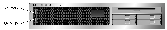
USB ports 2 and 3 are located on the front panel (FIGURE 1-3).
FIGURE 1-3 Front Panel USB Ports
Cabling Notes
- Minimum cable connections for the server:
- At least one system on-board Ethernet network connection (NET port)
- The system controller serial management port (SER MGT port)
- The system controller network management port (NET MGT port)
- Power cables for the two system power supplies
- System controller (SC) management ports: There are two SC management ports for use with the ALOM CMT system controller.
- The SC serial management port (labeled SER MGT) uses an RJ-45 cable and is always available. This is the default connection to the ALOM CMT system controller.
- The SC network management port (labeled NET MGT) is the optional connection to the ALOM CMT system controller. This port is not available until you have configured network settings for the system controller (through the SC serial management port). See Enabling the System Controller Network Management Port. The SC network management port uses an RJ-45 cable for a 10/100 BASE-T connection. This port does not support connections to Gigabit networks.
- See the Sun SPARC Enterprise T2000 Server Overview for more information.
- Ethernet ports are labeled NET0, NET1, NET2, and NET3. The Ethernet interfaces operate at 10 Mbps, 100 Mbps, and 1000 Mbps. The transfer rates for the Ethernet ports are given in .
TABLE 1-1 Ethernet Connection Transfer Rates
|
Connection Type
|
IEEE Terminology
|
Transfer Rate
|
|
Ethernet
|
10BASE-T
|
10 Mbit/sec
|
|
Fast Ethernet
|
100BASE-TX
|
100 Mbits/sec
|
|
Gigabit Ethernet
|
1000BASE-T
|
1000 Mbit/sec
|
- TTYA serial port: Use the DB-9 connector with a null modem cable for serial devices. This port appears as ttya in Solaris OS and OpenBoot messages. This port is not connected to the SC serial management port.
- USB Ports: USB ports support hot-plugging. You can connect and disconnect USB cables and peripheral devices while the system is running, without affecting system operations.
- You can only perform USB hot-plug operations while the OS is running. USB hot-plug operations are not supported when the system ok prompt is displayed or before the system has completed booting.
- You can connect up to 126 devices to each of the two USB controllers, for a total of 252 USB devices per system.
- AC power cables: Do not attach power cables to the power supplies until you have finished connecting the data cables, and have connected the server to a serial terminal or a terminal emulator (PC or workstation). The server goes into standby mode and the ALOM CMT system controller initializes as soon as the AC power cables are connected to the power source. System messages may be lost after 60 seconds if the server is not connected to a terminal, PC, or workstation.
Slide Rail Assembly Notes
The rackmount kit has two slide rail assemblies. A slide rail assembly can be installed on either the right or left side of the rack.
Each slide rail assembly consists of a three-section slide rail and a removeable mounting bracket (FIGURE 1-4).
FIGURE 1-4 Sections of the Slide Rail Assembly

- The front, middle, and rear sections form the slide rail. The middle and rear sections have holes for mounting screws and adjust to fit rack depths from 24 in (61 cm) to 36.5 in (93 cm). The front section can be extended to allow movement of the server out of the rack.
- The removeable mounting bracket slides 14 in (36 cm) out of the slide rail, then locks in place. If you unlock the mounting bracket at this point, it slides an additional 12 in (30 cm) before separating from the slide rail. You can then mount the mounting bracket to the right or left side of the server chassis.
- Note that there are a total of five locks (FIGURE 1-5) in a slide rail assembly. Four are on the mounting bracket. One lock is on the front section of the slide rail. The uses of these locks are described in the installation procedure in Chapter 2.
FIGURE 1-5 Locating the Locks on the Slide Rail Assembly

Safety Precautions

|
Caution - Deploy the anti-tilt bar on the equipment rack before beginning an installation.
|

|
Caution - The server weighs approximately 40 lb (18 kg). Two people are required to lift and mount the system into a rack enclosure when using the procedures in this chapter.
|


|
Caution - When completing a two-person procedure, always communicate your intentions clearly before, during, and after each step to minimize confusion.
|
| Sun SPARC Enterprise T2000 Server Installation Guide
|
819-7988-10
|
|
Copyright © 2007, Sun Microsystems, Inc. All Rights Reserved.