| C H A P T E R 5 |
|
Replacing Cold-Swappable FRUs |
This chapter describes how to remove and replace field-replaceable units (FRUs) in the server that must be cold-swapped.
The following topics are covered:
For a list of FRUs, see Appendix A.
Before you can remove and replace parts that are inside the server, you must perform the following procedures:
| Note - These procedures do not apply to the hot-pluggable and hot-swappable devices (fans, power supplies, hard drives, and rear blower) described in Chapter 4. |
The corresponding procedures that you perform when maintenance is complete are described in Section 5.3, Common Procedures for Finishing Up.
The server can be serviced with the following tools:
Performing a graceful shutdown ensures that all of your data is saved and the system is ready for restart.
1. Log in as superuser or equivalent.
Depending on the nature of the problem, you might want to view the system status, the log files, or run diagnostics before you shut down the system. Refer to the Sun Fire T2000 Server Administration Guide for log file information.
Refer to your Solaris system administration documentation for additional information.
3. Save any open files and quit all running programs.
Refer to your application documentation for specific information on these processes.
Refer to the Solaris system administration documentation for additional information.
5. Switch from the system console to the ALOM CMT sc> prompt by typing the #. (Hash-Period) key sequence.
d. At the ALOM CMT sc> prompt, issue the poweroff command.
Refer to the Advanced Lights Out Management (ALOM) CMT Guide for more information about the ALOM CMT poweroff command.
If the server is installed in a rack with the extendable slide rails that were supplied with the server, use this procedure to extend the server to the maintenance position.
| Note - Remove the server from the rack for all cold-swappable FRU replacement procedures except the DIMMs, PCI cards, and the system controller. |
1. (Optional) Issue the following command from the ALOM CMT sc> prompt to locate the system that requires maintenance.
Once you have located the server, press the Locator LED button to turn it off.
2. Check to see that no cables will be damaged or interfere when the server is extended.
Although the cable management arm (CMA) that is supplied with the server is hinged to accommodate extending the server, ensure that all cables and cords are capable of extending.
3. From the front of the server, release the slide rail latches on each side.
Pinch the green latches as shown in FIGURE 5-1.
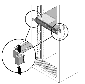
FIGURE 5-1 Slide Release Latches
4. While pinching the release latches, slowly pull the server forward until the slide rails latch.
Remove the server from the rack for all cold-swappable FRU replacement procedures except the DIMMs, PCI cards, and the system controller.

|
Caution - The serverweighs approximately 40 lb. (18 kg). Two people are required to dismount and carry the chassis. |
1. Disconnect all the cables and power cords from the server.
2. Extend the server to the maintenance position as described in Section 5.1.3, Extending the Server to the Maintenance Position.
3. Press the metal lever (FIGURE 5-2) that is located on the inner side of the rail to disconnect the CMA from the rail assembly (on the right side from the back of the rack).
This action leaves the CMA still attached to the cabinet, but the server chassis is now disconnected from the CMA.
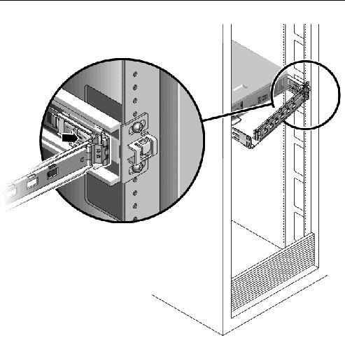
FIGURE 5-2 Locating the Metal Lever

|
Caution - The server weighs approximately 40 lb. (18 kg). The next step requires two people to dismount and carry the chassis. |
4. From the front of the server, pull the release tabs forward and pull the server forward until it is free of the rack rails.
The release tabs are located on each rail, about midway on the server.
5. Set the server on a sturdy work surface.

|
Caution - The system supplies standby power to the circuit boards even when the system is powered off. |
 Disconnect both power cords from the power supplies.
| Note - The following FRU replacements do not require that power be removed: DIMMs and PCI cards. |
1. Prepare an antistatic surface on which to set parts during removal and installation.
Place ESD-sensitive components such as the printed circuit boards on an antistatic mat. The following items can be used as an antistatic mat:
2. Attach an antistatic wrist strap.
When servicing or removing server components, attach an antistatic strap to your wrist and then to a metal area on the chassis. Do this after you disconnect the power cords from the server.
All field-replaceable units (FRUs) that are not hot-swappable require the removal of the top cover.
1. Press the top cover release button (FIGURE 5-3).
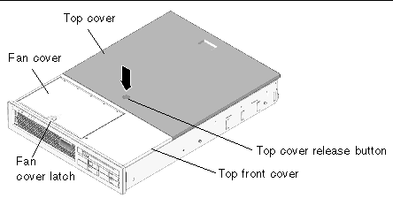
FIGURE 5-3 Top Cover and Release Button
2. While pressing the top cover release button, slide the cover toward the rear of the server about half of an inch.
3. Lift the cover off the chassis.
The following field-replaceable units (FRUs) require the removal of the top front cover and front bezel:
1. Remove the top cover as described in Section 5.1.7, Removing the Top Cover.
2. Lift the fan cover latch (FIGURE 5-3) and open the fan cover.
3. Loosen the captive screw (near the farthest right fan) that secures the bezel to the chassis (FIGURE 5-4).
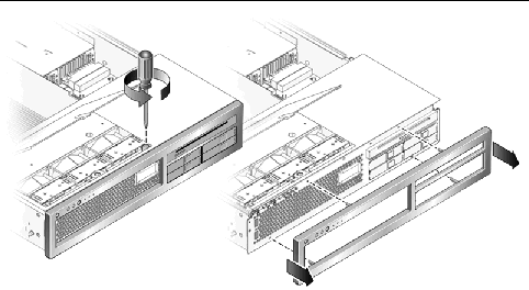
FIGURE 5-4 Removing the Front BezelFrom the Server Chassis
4. Remove the front bezel from the chassis (FIGURE 5-4).
The bezel is held in place by a mounting tab and four fasteners that clamp the bezel to the chassis.
5. While holding the fan cover open, slide the top front cover forward to disengage the top front cover from the chassis.
6. Lift the top front cover from the chassis.
This section provides procedures for replacing the following field-replaceable parts (FRUs) inside the server chassis:
To locate these FRUs, refer to Appendix A.
1. Perform the procedures described in Section 5.1, Common Procedures for Parts Replacement.
2. Locate the PCI card that you want to remove.
To locate the PCI card slots, refer to FIGURE 5-5 and FIGURE 5-6. The PCI card slots are located on the I/O portion of the motherboard assembly.

FIGURE 5-5 Location of PCI-Express and PCI-X Card Slots
3. Note where the PCI card is installed, and note any cables so you know where to reinstall the card and cables.
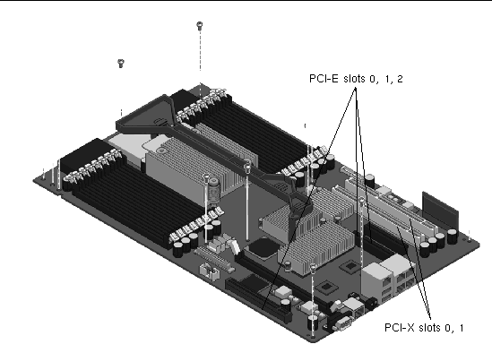
FIGURE 5-6 Location of PCI-Express and PCI-X Card Slots
4. Note and remove any cables that are attached to the card.
5. Rotate the PCI hold-down bracket 90 degrees so it no longer covers the PCI card (FIGURE 5-7).
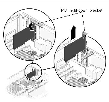
FIGURE 5-7 PCI Card and Hold-Down Bracket
6. Carefully pull the card out of the socket.
7. Place the card on an antistatic mat.
8. Rotate the hold-down bracket so that it does not protrude into the chassis.
1. Unpackage the replacement PCI-Express or PCI-X card and place it on an antistatic mat.
2. Locate the proper socket for the card you are replacing.
3. Rotate the PCI hold-down bracket 90 degrees so you can install the card.
4. Insert the card into the socket.
5. Rotate the PCI hold-down bracket 90 degrees to lock the card in place.
6. Perform the procedures described in Section 5.3, Common Procedures for Finishing Up.
| Note - Not all DIMMs detected as faulty and offlined by POST must be replaced. In service (maximum) mode, POST detects memory devices with errors that might be corrected with Solaris PSH. See Section 3.4.5, Correctable Errors Detected by POST. |

|
Caution - This procedurerequires that you handle components that are sensitive to static discharges that can cause the component to fail. To avoid this problem, ensure that you follow antistatic practices as described in Section 5.1.6, Performing Electrostatic Discharge Prevention Measures. |
1. Perform the procedures described in Section 5.1, Common Procedures for Parts Replacement.
2. Locate the DIMMs (FIGURE 5-8) that you want to replace.
Use FIGURE 5-8 and TABLE 5-1 to identify the DIMMs you want to remove.
| Note - For memory configuration information see Section 6.2.1, Memory Guidelines. |
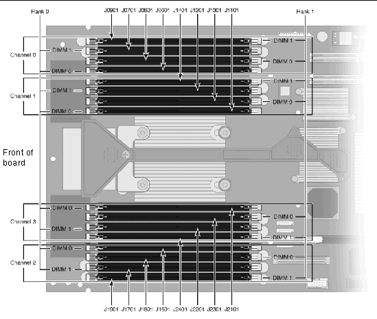
Use FIGURE 5-8 and TABLE 5-1 to map DIMM names that are displayed in faults to socket numbers that identify the location of the DIMM on the motherboard.
|
DIMM Name Used in Messages[1] |
|
|---|---|
3. Note the DIMM locations so you can install the replacement DIMMs in the same sockets.
4. Push down on the ejector levers on each side of the DIMM connector until the DIMM is released.
5. Grasp the top corners of the faulty DIMM and remove it from the system.
6. Place DIMMs on an antistatic mat.
1. Unpackage the replacement DIMMs and place them on an antistatic mat.
2. Ensure that the connector ejector tabs are in the open position.
3. Line up the replacement DIMM with the connector.
Align the DIMM notch with the key in the connector. This action ensures that the DIMM is oriented correctly.
4. Push the DIMM into the connector until the ejector tabs lock the DIMM in place.
5. Perform the procedures described in Section 5.3, Common Procedures for Finishing Up.
6. Gain access to the ALOM CMT sc> prompt.
Refer to the Sun Fire T2000 Advanced Lights Out Management (ALOM) Guide for instructions.
7. Run the showfaults -v command to determine how to clear the fault.
The method you use to clear a fault depends on how the fault is identified by the showfaults command.
sc> showfaults -v ID Time FRU Fault 0 SEP 09 11:09:26 MB/CMP0/CH0/R0/D0 Host detected fault, MSGID: SUN4V-8000-DX UUID: 7ee0e46b-ea64-6565-e684-e996963f7b86 |
Then run the enablecomponent command to enable the FRU:
8. Perform the following steps to verify the repair:
a. Set the virtual keyswitch to diag so that POST will run in Service mode.
c. Switch to the system console to view POST output.
Watch the POST output for possible fault messages. The following output is a sign that POST did not detect any faults:
d. Return the virtual keyswitch to normal mode.
e. Issue the Solaris OS fmadm faulty command.
No memory or DIMM faults should be displayed.
If faults are reported, refer to the diagnostics flowchart in FIGURE 3-1 for an approach to diagnose the fault.
9. Gain access to the ALOM CMT sc> prompt.
10. Run the showfaults command.
sc> showfaults -v ID Time FRU Fault 0 SEP 09 11:09:26 MB/CMP0/CH0/R0/D0 Host detected fault, MSGID: SUN4U-8000-2S UUID: 7ee0e46b-ea64-6565-e684-e996963f7b86 |
11. Run the clearfault command.
12. Switch to the system console.
13. Issue the fmadm repair command with the UUID.
Use the same UUID that you used with the clearfault command.

|
Caution - The system controller card can be hot. To avoid injury, handle it carefully. |
1. Perform the procedures described in Section 5.1, Common Procedures for Parts Replacement.
2. Locate the system controller card.
See Appendix A for an illustration of the servers FRUs that shows the system controller card.
3. Push down on the ejector levers on each side of the system controller until the card is released from the socket.
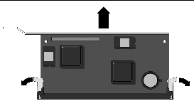
FIGURE 5-9 Ejecting and Removing the System Controller Card
4. Grasp the top corners of the card and pull it out of the socket.
5. Place the system controller card on an antistatic mat.
6. Remove the system configuration PROM (FIGURE 5-10) from the system controller and place it on an antistatic mat.
The system controller contains the persistent storage for the host ID and Ethernet MAC addresses of the system, as well as the ALOM CMT configuration including the IP addresses and ALOM CMT user accounts, if configured. This information will be lost unless the system configuration PROM is removed and installed in the replacement system controller. The PROM does not hold the fault data, and this data will no longer be accessible when the system controller is replaced.
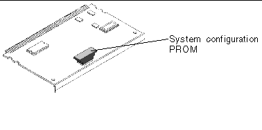
FIGURE 5-10 Locating the System Configuration PROM
1. Unpackage the replacement system controller card and place it on an antistatic mat.
2. Install the system configuration PROM that you removed from the faulty system controller card.
The PROM is keyed to ensure proper orientation.
3. Locate the system controller slot on the motherboard assembly.
4. Ensure that the ejector levers are open.
5. Holding the bottom edge of the system controller parallel to its socket, carefully align the system controller so that each of its contacts is centered on a socket pin.
Ensure that the system controller is correctly oriented. A notch along the bottom of the system controller corresponds to a tab on the socket.
6. Push firmly and evenly on both ends of the system controller until it is firmly seated in the socket.
You hear a click when the ejector levers lock into place.
7. Perform the procedures described in Section 5.3, Common Procedures for Finishing Up.
The motherboard for your server has two distinct boards for the CPU and the I/O board. However, they must be removed and replaced as a single motherboard assembly (FIGURE 5-11).

|
Caution - A flexible cable connects the CPU and I/O boards. This flexible cable is fragile. Handle these parts very carefully to prevent damage. |

|
Caution - This procedure requires that you handle components that are sensitive to static discharges that can cause the component to fail. To avoid this problem, ensure that you follow antistatic practices as described in Section 5.1.6, Performing Electrostatic Discharge Prevention Measures. |
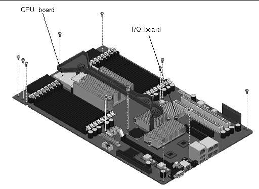
FIGURE 5-11 Motherboard Assembly
1. Perform the procedures described in Section 5.1, Common Procedures for Parts Replacement.
| Note - To avoid damage, ensure the front bezel and fan cover are completely removed before continuing. |
2. Remove all cables from the rear of the server.
Ensure that you remove all cables and power cords.
3. Remove any PCI option cards that are installed and then rotate the hold-down brackets so they do not protrude into the chassis.
4. Remove all DIMMs from the motherboard assembly.
See Section 5.2.3, Removing DIMMs.
Note the memory configuration so you can reinstall the memory in the replacement board.
5. Remove the system controller card from the motherboard assembly.
See Section 5.2.5, Removing the System Controller Card.
6. Disconnect cables from the motherboard assembly:
The SAS hard drive and the cable marked P8 pass through a cutout in the interior wall of the chassis. Before removing the motherboard assembly, ensure that these cables are out of the way. The SAS hard drive cables can be folded back over the interior wall or passed through the cutout (FIGURE 5-12). However, the cable marked P8 is large and contains a number of small wires. The cable will not easily pass through the cutout. While pushing and pulling the cables through the cutout be careful not to damage the wires.
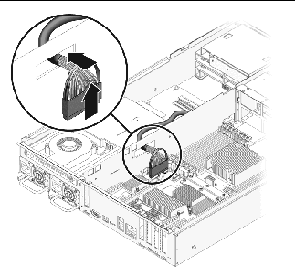
7. Remove the screws that secure the motherboard assembly to the chassis (FIGURE 5-13).

|
Caution - Do not remove the screws that hold the flexible cable in place. These screws must be installed at the factory, and they must not be removed. |
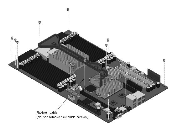
FIGURE 5-13 Location of the Screws in the Motherboard Assembly
8. Lift the front of the motherboard to clear the front standoffs.
The front of the motherboard refers to the part of the motherboard nearest the front of the server.
9. Slide the motherboard forward to clear the connectors from the cutouts in the rear of the chassis.
10. Using the handle, tilt the motherboard assembly over the interior chassis wall and lift it out of the chassis (FIGURE 5-14).

|
Caution - Do not lift the motherboard assembly over the front fan housing to remove it from the chassis, because doing so can damage the assembly. |
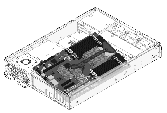
FIGURE 5-14 Removing the Motherboard Assembly From the Server Chassis.
11. Place the motherboard assembly on an antistatic mat.

|
Caution - A flexible cable connects the CPU and I/O boards. This flexible cable is fragile. Handle these parts very carefully to prevent damage. |

|
Caution - This procedure requires that you handle components that are sensitive to static discharges that can cause the component to fail. To avoid this problem, ensure that you follow antistatic practices as described in Section 5.1.6, Performing Electrostatic Discharge Prevention Measures. |
1. Unpackage the replacement motherboard assembly and place it on an antistatic mat.
2. Tilt the motherboard assembly over the interior wall into the chassis (FIGURE 5-15) and place it down on the rear standoffs
Avoid touching the front standoffs with the motherboard.
3. Slide the motherboard backward on the rear standoffs to engage the connectors in the rear cutouts.
4. Place the front of the motherboard down on the front standoffs.
The front of the motherboard refers to the part of the motherboard nearest the front of the server.
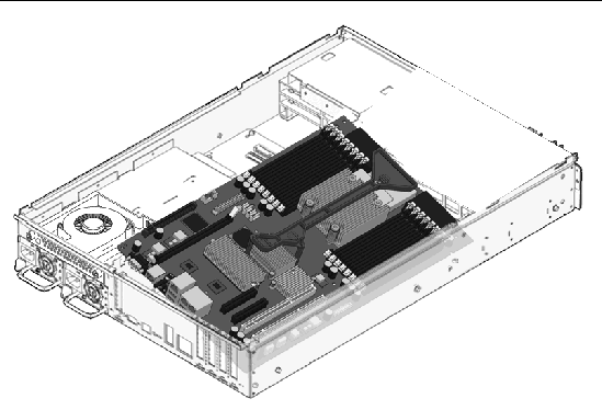
FIGURE 5-15 Installing the Motherboard Assembly
5. Adjust the position of the motherboard assembly so that it is mounted on the bus bar.
6. Adjust the position of the motherboard assembly so that it lines up with the standoff screw holes.
7. Loosely install two screws shown in FIGURE 5-16.
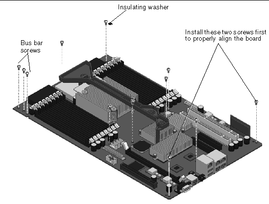
FIGURE 5-16 Securing the Motherboard Assembly to the Chassis
8. Secure the motherboard assembly to the chassis with the remaining screws and an insulating washer (FIGURE 5-16).
Do not fully tighten any screws until all of the screws are loosely installed.
One insulating washer is required in the position shown in FIGURE 5-16. A washer is supplied with the replacement FRU. Install the washer in this position even if the original motherboard did not have a washer.
9. Tighten the two bus bar screws to secure the bus bar to the motherboard assembly.
10. Reinstall the system controller card in the motherboard assembly.
See Section 5.2.6, Replacing the System Controller Card.
11. Reinstall all DIMMs in the motherboard assembly in the slots from which they were removed.
See Section 5.2.4, Replacing DIMMs.
12. Reinstall any PCI option cards that were removed.
See Section 5.2.2, Replacing PCI Cards.
13. Reconnect the cables to the motherboard:
14. Reconnect all cables that were removed from the rear of the server.
15. Perform the procedures described in Section 5.3, Common Procedures for Finishing Up.
The power distribution board (PDB) provides the circuitry that distributes power to the other components in the system. The PDB also contains an electronic copy of the chassis serial number (see Section 2.3, Obtaining the Chassis Serial Number). When you replace this board, you must run certain service commands to update the replacement PDB with the chassis serial number. The steps to perform these service commands are provided in Section 5.2.10, Replacing the Power Distribution Board.
1. Perform the procedures described in Section 5.1, Common Procedures for Parts Replacement.
2. Disengage both power supplies from the power distribution board.
To disengage a power supply, push the power supply latch to the right and pull the power supply out a few inches to disengage it from the PDB (FIGURE 5-17).

FIGURE 5-17 Location of Power Supply Latch
3. Disconnect all cables from the PDB:
4. Remove the two screws that secure the power distribution board to the bus bar (FIGURE 5-18).
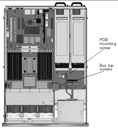
FIGURE 5-18 Location of Bus Bar Screws on the Power Distribution Board and the Motherboard Assembly
5. Remove the screw (FIGURE 5-19) that secures the power distribution board to the chassis.
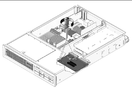
FIGURE 5-19 Removing the Power Distribution Board
6. Slide the power distribution board toward the front of the chassis and remove it from the chassis (FIGURE 5-19).
7. Place the power distribution board on an antistatic mat.
1. Loosely fit the power distribution board (PDB) onto the locator pins in the chassis and slide the board toward the rear of the chassis.
2. Secure the PDB to the chassis with the mounting screw.
3. Secure the PDB to the bus bar with two screws, and tighten all three screws (FIGURE 5-20).
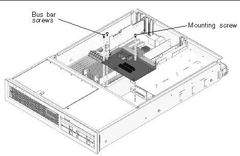
FIGURE 5-20 Installing the Power Distribution Board
4. Connect the cables to the power distribution board:
5. Re-engage the power supplies with the power distribution board connectors.
6. Note the chassis serial number.
The chassis serial number is located on a sticker on the front of the server and on a sticker on the side of the server. The serial number is unique to each server. You need this number for subsequent steps in this procedure.
7. Perform the procedures described in Section 5.3, Common Procedures for Finishing Up, and then return to this procedure to complete the remaining steps.
8. Gain access to the ALOM CMT sc> prompt.
9. Perform the following service commands to set the electronic chassis serial number in the power distribution board:
1. Perform the procedures described in Section 5.1, Common Procedures for Parts Replacement.
See Section 4.2.1, Removing a Fan.
3. Remove the screws that secure the LED board to the chassis (FIGURE 5-21).
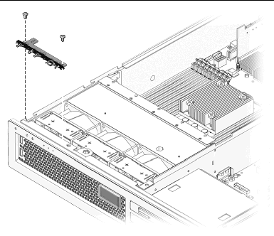
FIGURE 5-21 Removing the LED Board From the Chassis
4. Slide the LED board to the right to disconnect it from the front I/O board.
5. Remove the LED board from the chassis and place it on an antistatic mat.
1. Install the LED board in the chassis.
2. Slide the board to the left to connect it to the front I/O board.
3. Secure the LED board to the chassis using two M3x6 flat-head screws (FIGURE 5-21).
See Section 4.2.2, Replacing a Fan.
5. Perform the procedures described in Section 5.3, Common Procedures for Finishing Up.
1. Perform the procedures described in Section 5.1, Common Procedures for Parts Replacement.
See Section 4.2.1, Removing a Fan)
3. Remove the screw that secures the fan power board to the chassis (FIGURE 5-22).
4. Slide the fan power board to the right to disengage it from the front I/O board.
5. Remove the fan power board from the front fan bay and place the board on an antistatic mat.
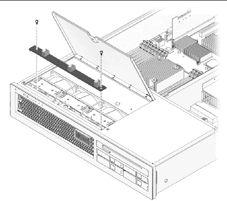
FIGURE 5-22 Removing the Fan Power Board
1. Unpackage the replacement fan power board and place it on an antistatic mat.
2. Lower the board into place and slide the board to the left to plug it into the front I/O board.
3. Secure the board to the chassis with the screws.
See Section 4.2.2, Replacing a Fan.
5. Perform the procedures described in Section 5.3, Common Procedures for Finishing Up.
1. Perform the procedures described in Section 5.1, Common Procedures for Parts Replacement.
See Section 4.2.1, Removing a Fan.
3. Disengage the fan power board from the front I/O board
Step 3 and Step 4 in Section 5.2.13, Removing the Fan Power Board.
4. Remove the fan guard to gain access to the M3x6 flat-head screw that secures the front I/O board to the chassis.
a. Remove the screw that secures the fan guard to the chassis.
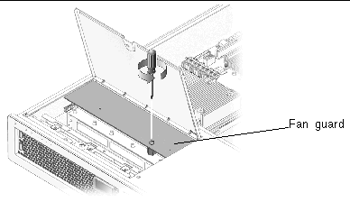
FIGURE 5-23 Removing the Fan Guard
b. Remove the fan guard from the chassis.
5. Disconnect the front I/O board data cable.
6. Remove the LED board. See Section 5.2.11, Removing the LED Board.
7. Remove the screw that secures the front I/O board to the chassis.
8. Slide the front I/O board back, tilt it up, clear the two mounting tabs in the front, and lift the board straight out of the chassis (FIGURE 5-24).
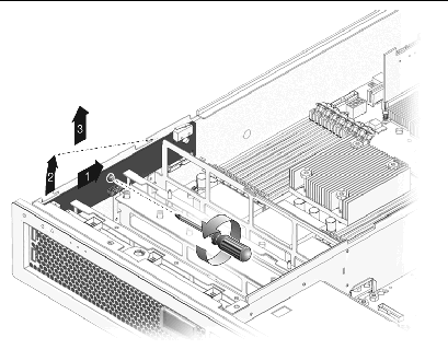
FIGURE 5-24 Removing the Front I/O Board
9. Place the front I/O board on an antistatic mat.
1. Unpackage the front I/O board and place it on an antistatic mat.
2. Tip the front I/O board downwards and slightly forward, and push it into place, aligning the board with the screw hole in the exterior wall of the chassis.
When the board is fully seated, both connectors on the USB ports are mounted flush against the motherboard assembly.
3. Using the screw, secure the front I/O board to the chassis.
4. Reconnect the front I/O board data cable.
See Section 5.2.12, Replacing the LED Board.
6. Reconnect and secure the fan power board.
See Section 4.2.2, Replacing a Fan.
8. Perform the procedures described in Section 5.3, Common Procedures for Finishing Up.
1. Perform the procedures described in Section 5.1, Common Procedures for Parts Replacement.
2. Remove the DVD interconnect board from the back of the DVD drive.
3. Press the release latch and pull the DVD drive out of the chassis.
1. Slide the DVD drive into the front of the chassis.
2. Replace the DVD interconnect board on the back of the DVD drive.
3. Perform the procedures described in Section 5.3, Common Procedures for Finishing Up.
1. Perform the procedures described in Section 5.1, Common Procedures for Parts Replacement.
2. Remove the DVD from the chassis.
See Section 5.2.17, Removing the DVD Drive.
3. Remove all hard drives from the chassis.
See Section 4.5.1, Removing a Hard Drive. Note the slot in which each drive belongs.
4. Disconnect the SAS power cable from the power cable plug.
5. Note of which SAS data cable is plugged into which slot and disconnect the four SAS data cables from the SAS disk backplane.
6. Remove the five screws that secure the SAS disk backplane to the chassis (FIGURE 5-25).
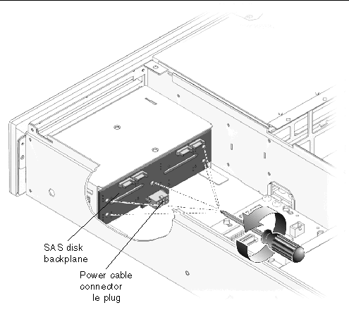
FIGURE 5-25 Removing the SAS Disk Backplane
7. Remove the SAS disk backplane from the chassis and place it on an antistatic mat.
1. Unpackage the replacement SAS disk backplane and place it on an antistatic mat.
2. Place the SAS disk backplane on the two ledges on the bottom of the drive cage assembly, with the power connector facing down toward the bottom of the chassis.
The ledges hold the backplane in place temporarily.
3. Secure the backplane to the drive cage assembly with five insulating washers and five screws (FIGURE 5-26).
Do not fully tighten any screws until all of the screws are loosely installed.
Insulating washers are supplied with the replacement FRU. Install one insulating washer with each screw even if the original SAS disk backplane did not have any washers.
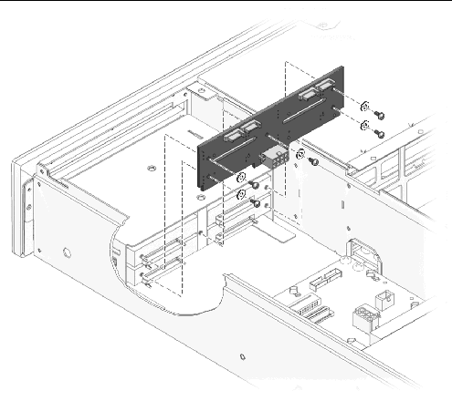
FIGURE 5-26 Replacing the SAS Disk Backplane
4. Connect the SAS power cable from the power cable connector.
5. Connect the four SAS data cables to the replacement SAS disk backplane, ensuring that you connect the cables in the same positions on the replacement SAS disk backplane.
6. Reinstall all four hard drives in the slots from which you removed them.
See Section 5.2.18, Replacing the DVD Drive.
8. Perform the procedures described in Section 5.3, Common Procedures for Finishing Up
1. Perform the procedures described in Section 5.1, Common Procedures for Parts Replacement.
2. Remove the system controller from the chassis (Section 5.2.5, Removing the System Controller Card) and place the system controller on an antistatic mat.
3. Using a small flat-head screwdriver, carefully pry the battery (FIGURE 5-27) from the system controller.
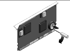
FIGURE 5-27 Removing the Battery From the System Controller
1. Unpackage the replacement battery.
2. Press the new battery into the system controller (FIGURE 5-28) with the positive side (+) facing upward (away from the card).
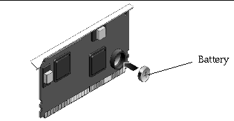
FIGURE 5-28 Replacing the Battery in the System Controller
3. Replace the system controller.
See Section 5.2.6, Replacing the System Controller Card.
4. Perform the procedures described in Section 5.3, Common Procedures for Finishing Up.
5. Use the ALOM CMT setdate command to set the day and time.
Use the setdate command before you power on the host system. For details about this command, refer to the Advanced Lights Out Management (ALOM) CMT Guide.
1. Place the top front cover on the chassis.
2. Slide the front top cover forward until it snaps into place, being careful to avoid catching the cover on the intrusion switch (FIGURE 5-29).
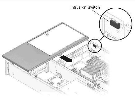
FIGURE 5-29 Replacing the Top Front Cover
3. Position the bezel on the front of the chassis and snap it into place.
5. Tighten the captive screw to secure the front bezel to the chassis.
1. Place the top cover on the chassis.
Set the cover down so that it hangs over the rear of the server by about an inch.
2. Slide the cover forward until it latches into place.
If you removed the server chassis from the rack, perform these steps.

|
Caution - The server weighs approximately 40 lb. (18 kg). Two people are required to carry the chassis and install it in the rack. |
1. Ensure that the rack rails are extended.
2. Place the ends of the chassis mounting brackets (inner section) into the slide rails (FIGURE 5-30).
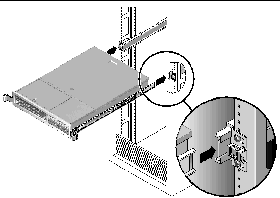
FIGURE 5-30 Returning the Server to the Rack
3. Slide the server into the rack until the brackets lock into place.
The server is now in the extended maintenace position.
If you extended the server to the maintenance position, use this procedure to return the server to the normal rack position.
1. Release the slide rails from the fully extended position by pushing the release levers on the side of each rail (FIGURE 5-31).
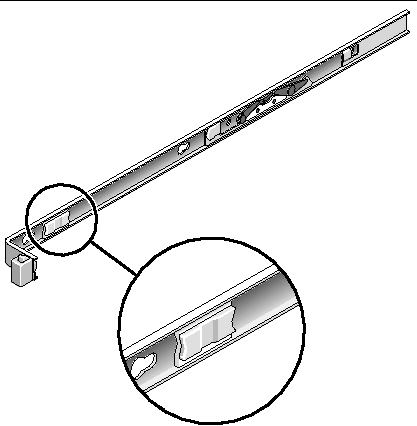
2. While pushing on the release levers, slowly push the server into the rack.
Ensure that the cables do not get in the way.
3. Reconnect the CMA into the back of the rail assembly:
| Note - Refer to the Sun Fire T2000 Server Installation Guide for detailed CMA installation instructions. |
a. Insert the inner latch (smaller, right side) into the clip located at the end of the mounting bracket (FIGURE 5-32).
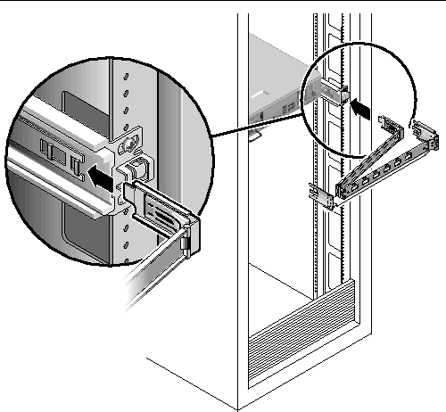
FIGURE 5-32 Installing the CMA
b. Plug the CMA rail extension into the end of the left slide rail assembly.
The tab at the front of the rail extension clicks into place.
4. Reconnect the cables to the back of the server.
If the CMA is in the way, disconnect the left CMA release and swing the CMA open.
 Reconnect both power cords to the power supplies.
| Note - As soon as the power cords are connected, standby power is applied, and depending on the configuration of the firmware, the system might boot. |
Copyright © 2007, Sun Microsystems, Inc. All Rights Reserved.