| C H A P T E R 6 |
|
Adding New Components and Devices |
This chapter describes how to add new components and devices to the server.
The following topics are covered:
Hot-pluggable devices, such as hard drives, require administration during installation.
Hot-swappable devices, such as USB devices, can be connected to, and disconnected from, the system while the system is running.
Other components and devices require you to shut down the system prior to installation. See Section 6.2, Adding Components Inside the Chassis.
Hard drives are physically addressed according to the slot in which they are installed. Depending on the server model, the hard drives might be connected to a PCI-X SAS controller card, or connected to a drive controller that is built into the motherboard (an onboard hard drive controller). Regardless of the type of controller, the hard drives are installed into the chassis the same way as described in this procedure.
| Note - Not all servers have the on-board hard drive controller support. These servers have the PCI-X SAS controller card installed. |
1. Remove the blank panel from the chassis:
a. On the blank panel, push the latch release button.
b. Grasp the latch and pull the blank panel out.
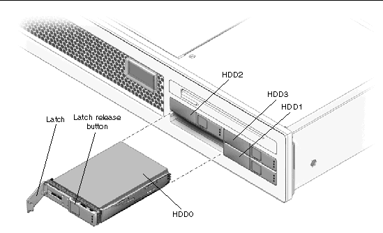
2. Align the disk drive to the drive bay slot.
See FIGURE 6-1. For additional details, see Section 4.5.1, Removing a Hard Drive.
3. Slide the hard drive into the bay until the drive is fully seated.
4. Close the hard drive lever to lock the drive in place.
5. Use cfgadm -al to list all disks in the device tree, including unconfigured disks.
If the disk is not in list, such as with a newly installed disk, then use devfsadm to configure it into the tree. See the devfsadm man page for details.

| Note - There are many USB devices on the market. Read the product documentation for your USB device for additional installation requirements and instructions that are not covered here. |
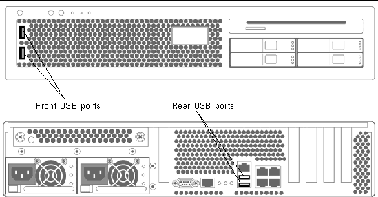
 Plug a standard USB device into one of the USB ports (FIGURE 6-2) on the front or rear of the server.

FIGURE 6-2 Adding a USB Device
You can add the following components to the server:
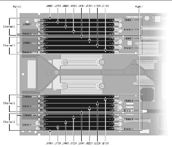
Use the following guidelines and FIGURE 6-3 and TABLE 6-1 to plan the memory configuration of your server.

1. Perform all of the procedures in Section 5.1, Common Procedures for Parts Replacement.
2. Unpackage the DIMMs and place them on an antistatic mat.
3. Ensure that the connector ejector tabs on the CPU board DIMM connectors are in the open position.
4. Line up the DIMM with the connector.
5. Push the DIMM into the connector until the ejector tabs lock the DIMM in place.
6. Repeat Step 3 through Step 5 for each additional DIMM.
7. Perform the procedures described in Section 5.1, Common Procedures for Parts Replacement.
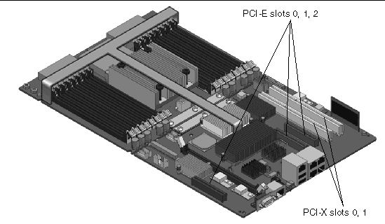
Follow these guidelines and FIGURE 6-4 to plan your configuration:

FIGURE 6-4 Location of PCI-Express and PCI-X Card Slots
1. Perform all of the procedures in Section 5.1, Common Procedures for Parts Replacement.
2. Rotate the PCI hold-down bracket (located on the edge of the chassis) 90 degrees so that the chassis edge can accept the card.
You might need to loosen the screw that holds the bracket to the chassis.
3. Line up the PCI card with the PCI connector on the rear of the motherboard.
4. Push the card into the connector so it is fully seated.
5. Rotate the PCI hold-down bracket to the closed position and secure the screw on the bracket.
6. Install any cables that go to the PCI card.
7. Perform the procedures described in Section 5.1, Common Procedures for Parts Replacement.
Copyright © 2007, Sun Microsystems, Inc. All Rights Reserved.