| C H A P T E R 2 |
|
Installing the Netra CP2500 Rear Transition Module |
This chapter describes how to install the Netra CP2500 RTM card.
This chapter contains the following sections:
The RTM-H is designed to be operated solely in the host slot of the Netra CT 410 and 810 servers. The RTM-H will not operate in a cPSB chassis, and it is not supported in any other CompactPCI server.
The RTM-S card can operate in either a Netra CT 410 or 810 server satellite slot or in a node slot of cPSB chassis. When installing a Netra CP2500 board into a cPSB chassis, you must use either this RTM-S or a custom-designed RTM.
|
Note - Before installing the RTM card, verify the card's part number to ensure that you are installing the correct RTM in the correct slot. For information on identifying the RTM, see Part Number, Serial Number, and Revision Number Identification. |
The Netra CP2500 RTM-S module has two DIP switch banks (S1301 and S1302) that control the Ethernet network traffic through the RTM-S module. By default, the switches on these banks are all set to the ON position. In the ON position, all network traffic gets routed out through the module's RJ-45 connectors. When these switches are set to the Off position, all network traffic is routed to the cPSB backplane network. Before installing the RTM-S into a cPSB chassis, set the switches in S1301 and S1302 to the Off position.
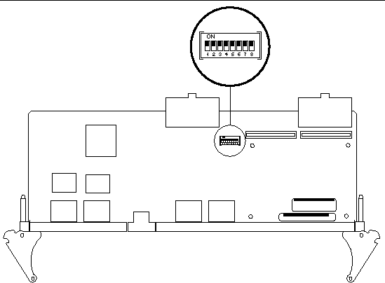
FIGURE 2-1 shows the location of the S1301 DIP switch bank, which is located on the component side of the RTM-S, and TABLE 2-1 describes the S1301 DIP switch settings. The S1301 DIP switch bank controls the network traffic of the ENET0 ports.
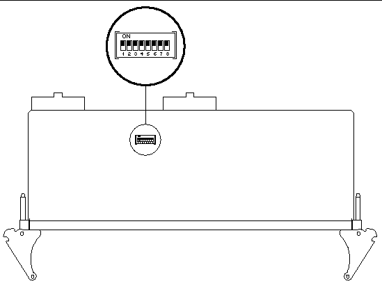
FIGURE 2-2 shows the location of the S1302 DIP switch bank, which is located on the solder side of the RTM-S, and TABLE 2-2 describes the S1302 DIP switch settings. The S1302 DIP switch bank controls the network traffic of the ENET1 ports.

|
Caution - Neverset the DIP switches on the Netra CP2500 RTM-H module. Sun does not support changing the RTM-H DIP switches from their default settings. |


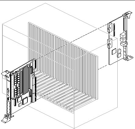
The RTM-S can be installed into a cPSB chassis with a backplane made for front and rear board installation (FIGURE 2-3). It must be installed in the slot directly behind the Netra CP2500 board for proper operation. These back-to-back slots have common pins to enable passing of signals.

The placement and order of installation for the Netra CP2500 RTM-S depends on system conditions:

|
Caution - You can install the The Netra CP2500 RTM card and the corresponding Netra board while the chassis is powered - however only start with a powered chassis if you must do so. |
|
The following procedure lists the general steps required for installing the Netra CP2500 rear transition module into a generic cPSB chassis. Always refer to the cPSB chassis documentation for chassis-specific cPSB card installation instructions.
1. Ensure that power is disconnected from the chassis.
When the cPSB system is off, the Netra CP2500 RTM card can be inserted either before or after installing the mating Netra CP2500 board.
The Netra CP2500 RTM card is not hot-swappable. The transition card's entire power comes from its associated Netra CP2500 board (see also Power Requirements and Electrical Requirements).
2. Check the positioning of the Netra CP2500 RTM card extraction levers.
Ensure that the Netra CP2500 RTM card extraction levers are aligned perpendicular to the card flange.
3. Install the Netra CP2500 RTM card into the chassis rear connector slot that lines up directly with the Netra CP2500 board (FIGURE 2-3).
a. Position the card with its CompactPCI RJ5 connector (labeled J0401 on the transition card) on top.
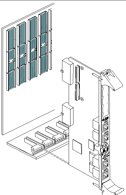
b. Engage the board edges with the chassis card guides and slide it into the chassis (FIGURE 2-4).
c. Using the ejector handles, gently push the card into alignment with the edges of the backplane pins, without touching the pins.
At this point, the card rear flange should project approximately 6 mm (1/4 inch) back from the seated position.
d. Gently apply pressure to engage the pins and seat the board.

4. Install the Netra CP2500 board into the front of the chassis (FIGURE 2-3) and push the board toward the backplane.
Ensure that the board is seated properly and that the connectors make good contact with the Netra CP2500 RTM card.
5. Install the supported peripheral devices at the transition module connector ports as required.
Use shielded cables for the ports on the transition module. The shield should be grounded at both ends. For further details on installation of the board, refer to the Netra CP2500 cPSB Board Installation and Technical Reference Manual (816-7186).
Refer to your system manual for instructions on correctly powering on the system.
Copyright © 2007, Sun Microsystems, Inc. All Rights Reserved.