C.1.10 Ethernet
The system unit supports 10-Mbps, 10BASE-T, twisted-pair Ethernet and 100-Mbps, 100BASE-TX, media independent interface (MII) Ethernet with the use of a single magnetics module. Twisted-pair Ethernet is provided through an 8-pin RJ45 connector. MII Ethernet is provided through a 40-pin MII connector. The MII port allows connection to any cable medium, including unshielded twisted-pair (UTP), shielded twisted-pair (STP), and fiber optic accompanied by the appropriate external transceiver. The system automatically senses an external transceiver, thus disabling an on-board transceiver.The Ethernet circuitry design is based on a Quality Semiconductor PHY.
The PHY chip integrates a 100BASE-TX physical coding sub-layer (PCS) and a complete 10BASE-T module in a single chip. It provides a standard MII to communicate between the physical signaling and the medium access control layers for both 100BASE-TX and 10BASE-T operations. The PHY IC interfaces to the 100-Mbps physical-medium-dependent transceiver Twister IC.
The 100BASE-TX portion of the PHY IC consists of the following functional blocks:
-
Transmitter
-
Receiver
-
Clock generation module
-
Clock recovery module
The 10BASE-T section of the PHY IC consists of the 10-Mbps transceiver module with filters.
The 100BASE-TX transceiver is included in a separate Twister IC and features adaptive equalization, baseline wander correction, and transition time control on the output signals.
The 100BASE-TX and 10BASE-T sections share the following functional characteristics:
-
PCS control
-
MII registers
-
IEEE 1149.1 controller (JTAG compliance)
-
IEEE 802.3u auto negotiation
The next sections provide brief descriptions of the following:
-
Automatic negotiation
-
External transceivers
-
External cables
-
Connectors
-
MII power
-
MII port timing
C.1.10.1 Automatic Negotiation
Automatic negotiation controls the cable when a connection is established to a network device. It detects the various modes that exist in the linked partner and advertises its own abilities to automatically configure the highest performance mode of inter-operation, namely, 10BASE-T, 100BASE-TX, or 100BASE-T4 in half- and full-duplex modes.
The Ethernet port supports automatic negotiation. At power up, an on-board transceiver advertises 100BASE-TX in half-duplex mode, which is configured by the automatic negotiation to the highest common denominator based on the linked partner.
C.1.10.2 External Transceivers
The following external transceivers are connected through the MII port:
-
6211 Micro 100BASE-FX FastEthernet transceiver
-
CT4-1030 100BASE-T4 transceiver
-
CFX-107X 100BASE-FX transceiver
-
XF467A MII-to-AUI transceiver
C.1.10.3 External Cables
The MII port supports an 18 inch (0.5-meter) long, 40-conductor, 20 signal-ground, STP cable. The single-ended impedance of the cable is 68 ohms (+/-10%). The propagation delay for each twisted-pair, measured from the MII connector to the PHY, does not exceed 2.5 nanoseconds.
The RJ45 Ethernet port supports a Category 5, UTP cable for the 100BASE-TX, and a Category 3, 4, or 5 UTP cable for the 10BASE-T operation.
Note -
The maximum cable segment lengths for the 100BASE-TX and 10BASE-TX are 300 feet (100 meters) and 3000 feet (1000 meters), respectively.
C.1.10.4 Connectors
A 40-pin connector is used for the MII connector. A standard 8-pin RJ45 connector with a shield is used for the AUI connector.
C.1.10.5 MII Power
A regulated 5-VDC (+/- 5%) voltage is supplied to the PHY IC over the load range of from 0 to 750 mA. A 2-amp overcurrent protection circuit is provided by a polymer-based resettable fuse to the MII supply voltage.
MII-to-AUI connection to a 10-Mbps medium attachment unit requires a supplemental power source to meet the AUI power supply requirements. The MII-AUI converter provides the necessary supplemental power.
C.1.10.6 MII Port Timing
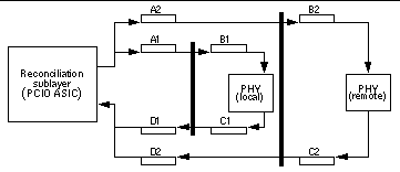
MII port timing encompasses two configurations involving the use of either an on-board transceiver or external transceivers. For either transceiver configuration, the MII port timing is the same because MII operates with a 40-nanosecond cycle time.
MII is used to interconnect both integrated circuits and circuit assemblies. This enables separate signal transmission paths to exist between the reconciliation sublayer, embedded in the PCIO ASIC, and a local PHY IC, and between the reconciliation sublayer and a remote PHY IC. The unidirectional paths between the reconciliation sublayer and the local PHY IC are composed of sections A1, B1, C1 and D1. The unidirectional paths between the reconciliation sublayer and the remote PHY IC are composed of sections A2, B2, C2, and D2.

- © 2010, Oracle Corporation and/or its affiliates
