


Chapter
2
Installing the System Into the Rack
Enclosure
This chapter provides step-by-step instructions for rackmounting the server into a Sun expansion cabinet or other EIA-compliant rack enclosure.
To rackmount a Sun Fire 280R server, complete the following tasks in the order listed:
The Sun Fire 280R Server Rackmounting Overview included with your documentation set illustrates the rackmounting steps in a convenient, graphical overview. This chapter provides detailed information about each step.
Many of the options ordered with your system are pre-installed at the factory. For information about how to install other options, see the Sun Fire 280R Server Service Manual or contact your qualified service provider. For information about installing one additional internal disk drive, see the Sun Fire 280R Server Owner's Guide.
- Unpack the system and verify the contents. See Chapter 1 for instructions.
- Unpack the accessory box and place the assembled slides and hardware on a clear work surface.
- Verify that you have the components and hardware shown in Accessory and Slide Assembly Box Contents.
- Read the rack enclosure requirements described in Appendix A of this guide to ensure that you meet the enclosure requirements.
- Read the safety precautions that follow the "Tools Required" section.
- For faster installation and setup, use two sets of the required tools. Two persons are required to install the server.
Tools Required
- Phillips No. 2 screwdriver
- Flat-blade screwdriver
- Set of appropriate Allen wrenches to remove the side panels on some rack enclosures
- Adjustable wrench to tighten the nuts on the mounting brackets
- Spirit level for leveling the rackmount enclosure front-to-back and
side-to-side (if necessary)
For a complete description of the safety precautions to follow when installing a Sun Fire 280R server, see the Sun Fire 280R Server Owner's Guide.
 Caution -
Install the system as low as possible into the rack enclosure. For the best stability, do not install the system above equipment that weighs less than the Sun Fire 280R server weight (a maximum of 75 lb/34 kg).
Caution -
Install the system as low as possible into the rack enclosure. For the best stability, do not install the system above equipment that weighs less than the Sun Fire 280R server weight (a maximum of 75 lb/34 kg).
 Caution -
The system is heavy. In the following procedures, two persons are required to move the system in the procedure. Two persons are also required to align and install the slide assemblies into the rack.
Caution -
The system is heavy. In the following procedures, two persons are required to move the system in the procedure. Two persons are also required to align and install the slide assemblies into the rack.

 Caution -
For proper ventilation, each system in the rack enclosure requires 28 square inches (181 square cm) of unrestricted airflow into the front of the system, and 23 square inches (148 square cm) of unrestricted exhaust port at the back of the system. Maintain a minimum 1.5 inches (3.8 cm) clearance between the system and any front or back doors. See Appendix A for more information.
Caution -
For proper ventilation, each system in the rack enclosure requires 28 square inches (181 square cm) of unrestricted airflow into the front of the system, and 23 square inches (148 square cm) of unrestricted exhaust port at the back of the system. Maintain a minimum 1.5 inches (3.8 cm) clearance between the system and any front or back doors. See Appendix A for more information.
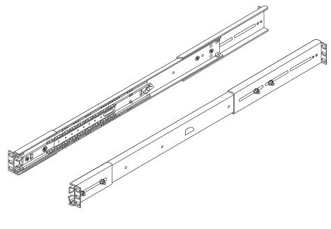
Below is a view of the assembled slide assembly. The rack installation is detailed in the following pages for the two slide assemblies.
- Open, and remove if applicable, the front and back doors of the rack enclosure.
- See the instructions provided with your rack enclosure.
- Stabilize the rack enclosure by extending its anti-tip legs or bolting the rack enclosure securely to the floor.
- See the instructions provided with your rack enclosure and read Appendix A.
- Remove the side panels from the rack enclosure, if applicable.
- See the instructions provided with your rack enclosure. Removing the side panels can improve access to the nuts and screws that you install when securing the system in the rack enclosure.
- Measure the depth of the rack enclosure.
- See "Vertical Mounting Rail Requirements" in Appendix A for more information about the range of depths in EIA-compliant industry-standard rack enclosures.
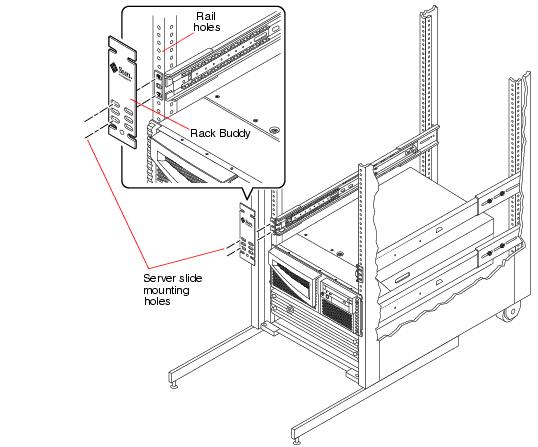
- Using a felt tip marker and the Rack Buddy, locate and mark the rack rail holes to use to attach each slide assembly.
- The Rack Buddy template can help you locate the rack rail holes to use for each slide assembly. The Rack Buddy is four rack units (7.0 inches/17.78 cm) or 12 holes tall. Because the rail holes on a standard rack enclosure are arranged in sets of three holes spaced 5/8ths, 5/8ths, and 4/8ths of an inch apart, which two holes of the three you use for attaching a slide assembly varies depending on exactly where in the rack the system is located.
- Examine the Rack Buddy. See the next figure.
- Two of the middle three pairs of holes are for mounting the slide bracket (you only use two screws in two of these three holes to attach each slide to the rack). The top and bottom openings in the template locate the system retainer screws that hold the system in the rack after it is installed.

- Place the Rack Buddy over the left front vertical rack rail. See the next figure.
- Move the bottom of the Rack Buddy to the location on the rack rail where the bottom of the system will be located.
- Adjust the Rack Buddy until the lower retainer opening is centered on the hole in the rail.
- Looking through the three middle holes on the Rack Buddy, locate and mark the two rack rail holes that are most visible through the template.
- Use these two rack rail holes to attach the slide assembly to the front rail. You will only use two of the three holes to attach the slide assembly. Mark the corresponding holes on the right front vertical rack rail.
You can either count the rack rail holes or use the Rack Buddy to make sure that each slide assembly is installed at the same height front-to-back and side-to-side in the rack. See Step5 of Prepare the Rack Enclosure for more information about using the Rack Buddy.
Before you begin the installation:
- Complete Prepare the Rack Enclosure.
- If this is the first system you are installing into the rack enclosure, use holes 9 and 10 or 11 (this assumes that an AC power sequencer occupies holes 1 through 6 in the bottom of the rack).
- Install the slide assemblies into the lowest available position.
- Install additional servers from the base up in the rack enclosure.
- If necessary, adjust the back mounting bracket forward or backward on the slide assembly to accommodate the depth of the rack.
- Use the depth you measured in Step4 of Prepare the Rack Enclosure.
- Secure the slide bracket assemblies to the front and back mounting rails using Phillips 10-32 panhead screws.
- Use the holes you marked in Step5 of Prepare the Rack Enclosure. Do not completely tighten the screws until after the server is installed. Ensure that all the screws are in place, and that the slide assemblies are secure and level.
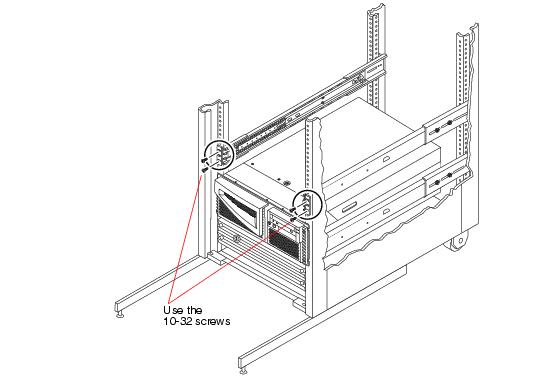
- Attach one slide assembly to the right rack mounting rail, and the other slide assembly to the left rack mounting rail. See the next figure.
- With the help of an assistant, position each slide assembly on the inside of the rack enclosure with the front (short) mounting bracket at the front of the rack.
- Using two Phillips 10-32 panhead screws, attach the front mounting bracket of one slide assembly to the front rail on the rack.
- Using two Phillips 10-32 panhead screws, attach the back (long) mounting bracket of the same slide assembly to the back rail of the rack (count the rack rail holes to ensure that you are matching the holes used on the front rail).
- Do not tighten the screws as far as they will go yet, but tighten them so that the assemblies are secure.
- Tighten the four 8-32 lock nuts that secure the back mounting brackets to the slide assemblies.
- Ensure that the back brackets are securely attached to each slide.
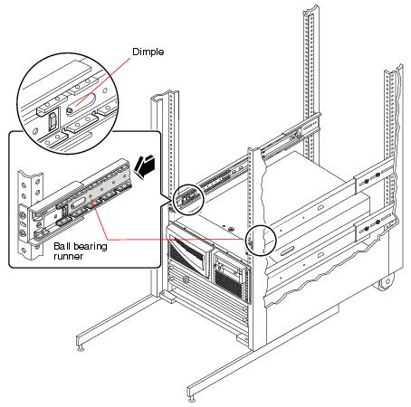
- Push each slide assembly into the rack until each assembly is fully retracted into the rack enclosure.
- Slide the ball-bearing runner forward until the dimple holds the runner in the forward position in each inner rail.
 Caution -
Ensure that each ball-bearing slide is secured at the front of each inner slide assembly before inserting any system into the slide assemblies. Verify that the inner slides are as far back as they can travel into the rack.
Caution -
Ensure that each ball-bearing slide is secured at the front of each inner slide assembly before inserting any system into the slide assemblies. Verify that the inner slides are as far back as they can travel into the rack.
 Caution -
The system is heavy. Two persons are required to move the system.
Caution -
The system is heavy. Two persons are required to move the system.
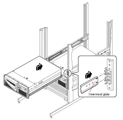
- Lift the server (one person on each side of the server) and approach the rack with the back of the server facing the front of the rack enclosure.
- Align the crimped ends of the innermost glides on the server with the slide bracket assemblies in the rack enclosure.
- Holding the server level, slide it evenly into the rack enclosure until the innermost glides stop in the slides.
- The innermost glides are factory installed on the sides of the server enclosure.
- On each side of the enclosure, press the flat spring catch mounted on each innermost glide and slide the server all the way into the rack.
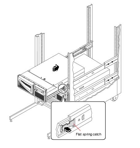
Slide the server in and out slowly and carefully to ensure that the slide assemblies and the innermost glides are working correctly.
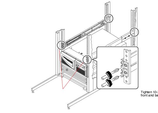
- Completely tighten all of the slide assembly rackmounting screws.
- Make sure that the slide assemblies are level front-to-back and left-to-right.
- Tighten the eight 10-32 screws that secure the slide assemblies to the vertical rack rails.
-
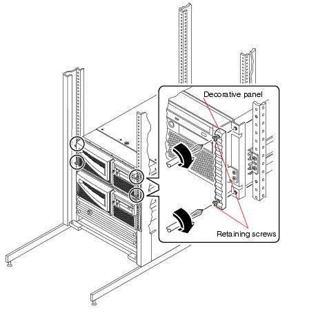
- Secure the server to the rails.
- Using the decorative panel retaining screws, secure the top and bottom of the system to the rails.
Copyright © 2001 Sun Microsystems, Inc. All Rights Reserved.