| Sun Fire V125 Server Administration Guide
|
   
|
This chapter describes the Sun Fire V125 server and contains an overview of the following main features:
Bezel Features
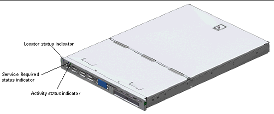
The front bezel of the Sun Fire V125 server contains the server status indicators and a space for placing an identification label.
FIGURE 1-1 Location of Status Indicators

Server Status Indicators
The server has three status indicators. They are located on the front bezel, and repeated on the back panel. A summary of the indicators is given in TABLE 1-1.
TABLE 1-1 Server Status Indicators
|
Indicator
|
LED color
|
LED State
|
Meaning
|
|
Activity
|
Green
|
On
|
The server is powered up and running the Solaris OS.
|
|
|
|
Off
|
Either power is not present, or Solaris OS is not running.
|
|
Service Required
|
Yellow
|
On
|
The server has detected a problem and requires the attention of service personnel.
|
|
|
|
Off
|
The server has no detected faults.
|
|
Locator
|
White
|
On
|
Identifies the server from others in a rack.
|
Table describes operation of activity, service required, and locator indicators used on the Sun Fire V125 server.
You can turn the Locator indicator on and off either from the system console or the Sun Advanced Light Out Manager (ALOM) command-line interface (CLI).
 To Turn the Locator Indicator On To Turn the Locator Indicator On
|
 Do one of the following:
- At the ALOM command-line interface, type:
 To Turn the Locator Indicator Off To Turn the Locator Indicator Off
|
 Do one of the following:
- At the ALOM command-line interface, type:
 To Display Locator Indicator Status To Display Locator Indicator Status
|
 Do one of the following:
- At the ALOM command-line interface, type:
Front Panel
Access the front panel by opening the bezel, which you do by pressing the release buttons on each side and rotating the bezel forward.
The front panel contains the following:
- On/Standby button
- Hard drive
- System configuration card
On/Standby Button
The On/Standby button controls only the power state of the server; it does not isolate the server from its electrical power source. The On/Standby button is a momentary switch that you can operate two ways:
- Press and immediately release
- Press and hold down for more than 4 seconds
The results of these actions are summarized in TABLE 1-2.
TABLE 1-2 On/Standby Switch Actions and Results
|
Server Power State
|
Press and Release
|
Press Down for More Than 4 Seconds
|
|
On (with Solaris OS running)
|
Software performs orderly shutdown. Server enters Standby state.
|
Server enters Standby state directly.
|
|
On (with Solaris OS not running)
|
No effect.
|
Server enters Standby state directly.
|
|
Standby
|
Server enters On power state.
|
Server enters On power state.
|
Table describes power states of the server when running Solaris OS, not running Solaris OS, or in standby.Controlling Server Power States
The server immediately goes into Standby mode as soon as it is connected to a power source. As long as it remains connected to the power source, the server stays in either the Standby or On power state. An explanation of the power states is given in TABLE 1-3.
TABLE 1-3 Explanation of Power States
|
Power State
|
Description
|
|
On
|
Server is connected to a power source and the power is enabled.
|
|
Standby
|
Server is connected to a power source but power is not enabled.
|
|
Off
|
Server is not connected to a power source. Power cable is disconnected.
|
Table describes on, standby, and off power-states for the server.
|
Note - The only way to completely remove power from the server is to disconnect the power cable.
|
Hard Drive
The Sun Fire V125 server ships with one hard drive; however, the server has slots for two hard drives. The slots accept any Sun LVD SCSI hard drive conforming to the 1-inch SCA-2 form factor.
The hard drive has two indicators associated with it. See TABLE 1-4 for a summary of what the indicators mean.
TABLE 1-4 Hard Drive Service Indicators
|
Indicator
|
LED color
|
LED State
|
Component Status
|
|
Activity
|
Green
|
Flashing
|
Active SCSI transactions
|
|
|
Off
|
No activity
|
|
Ready to Remove
|
Blue
|
On
|
Ready to remove
|
|
|
|
Off
|
Not ready to remove
|
Table describes component status of green Activity and blue Ready to Remove LEDs, when the LEDs are on, off, and flashing.
For information on removing and replacing a hard drive, see Removing and Replacing the Hard Drive.
DVD Drive
The Sun Fire V125 server contains a bay to accept an optional slimline ATAPI DVD drive. The bay is located on the front panel and is accessed by opening the bezel.
For information on DVD drive installation, see Removing and Replacing the DVD Drive.
System Configuration Card
The system configuration card (SCC) is housed in a slot behind the front bezel, next to the On/Standby button. The card contains unique network identity information, including the MAC address and host ID (known as the IDPROM), and the OpenBoot PROM configuration (also known as NVRAM).
The server attempts to access the SCC while booting.
- If a properly formatted card is not present in the reader, the system does not boot.
- If the content of the NVRAM section is invalid, the system is not initialized with its default NVRAM configuration.
It is essential that you store the SCC safely if you have to remove it from the server, and replace it before restarting the system.
For more information, see Swapping a System Configuration Card Between Servers.
TABLE 1-5 OpenBoot PROM Configuration Parameters Stored on the System Configuration Card
|
Parameter
|
Default
|
Description
|
|
diag-passes
|
1
|
Defines the number of times self-test methods are performed.
|
|
asr-policy
|
normal
|
Defines the policy implemented by asr-package.
|
|
test-args
|
None
|
Defines the test arguments to be used by the obpdiag tests.
|
|
local-mac-address?
|
true
|
If true, network drivers use their own MAC address, not the server's.
|
|
fcode-debug?
|
false
|
If true, includes name fields for plug-in device FCodes.
|
|
ttyb-rts-dtr-off
|
true
|
If true, operating system does not assert RTS and DTR on TTYB port.
|
|
ttyb-ignore-cd
|
false
|
If true, operating system ignores carrier-detect on TTYB
|
|
ttya-rts-dtr-off
|
true
|
If true, operating system does not assert RTS and DTR on TTYA port.
|
|
ttya-ignore-cd
|
|
If true, operating system ignores carrier-detect on TTYA port.
|
|
silent-mode?
|
false
|
Suppresses all messages if true and diag-switch? is false.
|
|
scsi-initiator-id
|
7
|
SCSI-ID of the SCSI controller.
|
|
oem-logo?
|
false
|
If true, uses custom OEM logo, otherwise, use Sun logo.
|
|
oem-banner?
|
false
|
If true, uses custom OEM banner.
|
|
ansi-terminal?
|
true
|
If true, printable characters are displayed and control characters are interpreted.
|
|
verbosity
|
normal
|
Defines the POST and obpdiag verbosity level.
|
|
screen-#columns
|
80
|
Sets number of columns on the screen.
|
|
screen-#rows
|
34
|
Sets number of rows on the screen.
|
|
ttya-mode
|
9600,8,n,1,-
|
TTYA (baud rate, no bits, parity, no stop, handshake).
|
|
ttyb-mode
|
9600,8,n,1,-
|
TTYB (baud rate, no bits, parity, no stop, handshake).
|
|
output-device
|
ttya
|
Power-on output device.
|
|
input-device
|
ttya
|
Power-on input device.
|
|
load-base
|
16384
|
Address from which data is read from a device.
|
|
auto-boot?
|
true
|
If true, system boots automatically to OS after power on or reset occurs.
|
|
boot-command
|
boot
|
Action following a boot command.
|
|
diag-file
|
none
|
File from which to boot if diag-switch? is true.
|
|
diag-device
|
net
|
Device to boot from if diag-switch? is true.
|
|
boot-file
|
none
|
File to boot if diag-switch? is false.
|
|
boot-device
|
disk net
|
Device or devices from which to boot if diag-switch? is false.
|
|
use-nvramrc?
|
false
|
If true, executes commands stored in NVRAM during server start-up.
|
|
nvramrc
|
none
|
Command script to execute if use-nvramrc? is true.
|
|
security-mode
|
none
|
Firmware security level (options: none, command, or full).
|
|
security-password
|
none
|
Firmware security password if security-mode is not none (never displayed) - do not set this directly.
|
|
security-#badlogins
|
none
|
Number of incorrect security password attempts.
|
|
diag-script
|
normal
|
Defines the script name to be executed by obpdiag.
|
|
diag-level
|
max
|
Defines how diagnostic tests are run (options are off, min, menu, and max).
|
|
diag-switch?
|
false
|
If true:
- Run in diagnostic mode.
- After a boot request, boot diag-file from diag-device.
If false:
- Run in nondiagnostic mode.
- Following a boot request, boot-file from boot-device.
|
|
diag-trigger
|
error-reset power-on-reset
|
Defines the type of system reset that will trigger POST and obpdiag operation.
|
|
service-mode?
|
false
|
Specifies the mode of operation for OBP, which can be normal or service.
|
|
error-reset-recovery
|
boot
|
Command to execute following a system reset generated by an error.
|
Table lists the OpenBoot PROM configuration parameters and default values that are stored on server's system configuration card. Table also describes system operation when default parameter values are initialized.
For additional information about OpenBoot PROM configuration parameters see:
http://www.sun.com/documentation
Search for the OpenBoot 4.x Command Reference Manual.
Back Panel Features
The server's I/O ports and power inlets are on the back panel.
FIGURE 1-2 I/O Ports

I/O Ports
The I/O ports on the back of the Sun Fire V125 server are arranged as shown in FIGURE 1-2. For more information on the I/O ports, refer to the Sun Fire V125 Server Getting Started Guide.
Network Status Indicators
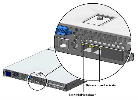
Each network connector has two status indicators.
FIGURE 1-3 Location of Network Status Indicators

The network status indicators convey:
- Network link status
- Network speed status (does not apply to the NET MGT port)
For a summary of what the Network Link status indicators mean, see TABLE 1-6.
TABLE 1-6 Network Link Indicators
|
Indicator color
|
LED State
|
Network Link Status
|
|
Green
|
On
|
Link is established.
|
|
|
Blinking
|
Link is transferring data.
|
|
|
Off
|
Link is not established.
|
Table describes network link status when the green LED is on, blinking, or off.
For a summary of what the network speed indicators mean, see TABLE 1-7.
TABLE 1-7 Network Speed Indicators
|
Indicator color
|
LED State
|
Network Speed Status
|
|
Green
|
On
|
The network link is established and running at its maximum supported speed.
|
|
|
Off
|
- If the network activity indicator is on, the network link is established but not running at its maximum supported speed.
- If the network activity indicator is off, network link is not established.
|
Table describes the network speed status when the green Network Speed indicator is on or off.USB Ports
The server has two USB ports for attaching supported USB devices. The ports are USB 1.1 compliant. They support device speeds of 1.5 Mbit/sec and 12 Mbit/sec, and a 5V supply is available at each connector to power the external device.
External SCSI Port
The SCSI port is a multimode Ultra160 SCSI interface. To operate at Ultra160 SCSI speeds, it must be in Low Voltage Differential (LVD) mode. If a single-ended device is connected to the server, it automatically switches to single-ended mode.
Power Supply Unit
The Sun Fire V125 server has one PSU and two associated status indicators. TABLE 1-8 summarizes the function of the indicators.
TABLE 1-8 Power Supply Unit Indicators
|
Indicator color
|
LED State
|
Component Status
|
|
Green
|
On
|
Power is present, and the PSU is active.
|
|
|
Off
|
Either power is not present, or the PSU has shut down due to an internal protection event.
|
|
Amber
|
On
|
The PSU has shut down due to an internal protection event and requires service attention.
|
|
|
Off
|
The PSU is operating normally.
|
Table describes component status of green and amber power supply indicators in on and off states.

|
Caution - As long as AC power is supplied to the server, potentially dangerous voltages might be present within the server.
|
System Prompts
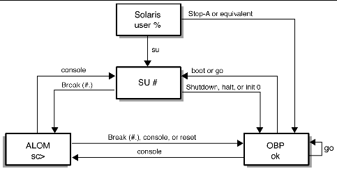
The following default server prompts are used by the Sun Fire V125 server:
- ok - OpenBoot PROM prompt
- sc - Advanced Lights Out Manager (ALOM) prompt
- # - Solaris OS superuser (Bourne and Korn shell)
FIGURE 1-4 shows the relationship between the three prompts and how to change from one prompt to another.
FIGURE 1-4 System Prompt Flow Diagram

For additional information about obtaining switching from OpenBoot PROM to server console (sc) prompts see Basic ALOM Functions.
| Sun Fire V125 Server Administration Guide
|
819-7420-10
|
   
|
Copyright © 2006, Sun Microsystems, Inc. All Rights Reserved.


