| C H A P T E R 4 |
|
Configuring Hardware |
This chapter provides hardware configuration information for the Sun Fire V445 server.
Topics in this chapter include:
The system motherboard provides slots for up to four CPU/Memory modules. Each CPU/Memory module incorporates one UltraSPARC IIIi processor, and slots for up to four DIMMs. The CPUs in the system are numbered from 0 to 3, depending on the slot where each CPU resides.
| Note - CPU/Memory modules on a Sun Fire V445 server are not hot-pluggable or hot-swappable. |
The UltraSPARC IIIi processor is a high-performance, highly integrated superscalar processor implementing the SPARC V9 64-bit architecture. The UltraSPARC IIIi processor can support both 2D and 3D graphics, as well as image processing, video compression and decompression, and video effects through the sophisticated Visual Instruction Set extension (Sun VIS software). The VIS software provides high levels of multimedia performance, including two streams of MPEG-2 decompression at full broadcast quality with no additional hardware support.
The Sun Fire V445 server employs a shared-memory multiprocessor architecture with all processors sharing the same physical address space. The system processors, main memory, and I/O subsystem communicate via a high-speed system interconnect bus. In a system configured with multiple CPU/Memory modules, all main memory is accessible from any processor over the system bus. The main memory is logically shared by all processors and I/O devices in the system. However, memory is controlled and allocated by the CPU on its host module, that is, the DIMMs on CPU/Memory module 0 are managed by CPU 0.
The Sun Fire V445 server uses 2.5-volt, high-capacity double data rate dual inline memory modules (DDR DIMMs) with error-correcting code (ECC). The system supports DIMMs with 512-Mbyte, 1-Gbyte, and 2-Gbyte capacities. Each CPU/Memory module contains slots for four DIMMs. Total system memory ranges from a minimum of 1 Gbyte (one CPU/Memory module with two 512-Mbyte DIMMs) to a maximum of 32 Gbytes (four modules fully populated with 2-Gbyte DIMMs).
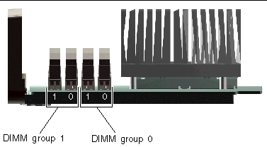
Within each CPU/Memory module, the four DIMM slots are organized into groups of two. The system reads from, or writes to, both DIMMs in a group simultaneously. DIMMs, therefore, must be added in pairs. The figure below shows the DIMM slots and DIMM groups on a Sun Fire V445 server CPU/Memory module. Adjacent slots belong to the same DIMM group. The two groups are designated 0 and 1 as shown in FIGURE 4-1.

FIGURE 4-1 Memory Module Groups 0 and 1
TABLE 4-1 lists the DIMMs on the CPU/Memory module, and to which group each DIMM belongs.
The DIMMs must be added in pairs within the same DIMM group, and each pair used must have two identical DIMMs installed - that is, both DIMMs in each group must be from the same manufacturer and must have the same capacity (for example, two 512-Mbyte DIMMs or two 1-Gbyte DIMMs).
| Note - Each CPU/Memory module must be populated with a minimum of two DIMMs, installed in either group 0 or group 1. |
For guidelines and complete instructions on how to install and identify DIMMs in a CPU/Memory module, refer to the Sun Fire V445 Server Service Manual and the Sun Fire V445 Server Installation Guide.
You can maximize the system's memory bandwidth by taking advantage of its memory interleaving capabilities. The Sun Fire V445 server supports two-way interleaving. In most cases, higher interleaving results in improved system performance. However, actual performance results can vary depending on the system application. Two-way interleaving occurs automatically in any DIMM bank where the DIMM capacities in DIMM group 0 match the capacities used in a DIMM group 1. For optimum performance, install identical DIMMs in all four slots in a CPU/Memory module.
Each Sun Fire V445 server CPU/Memory module contains an independent memory subsystem. Memory controller logic incorporated into the UltraSPARC IIIi CPU allows each CPU to control its own memory subsystem.
The Sun Fire V445 server uses a shared memory architecture. During normal system operations, the total system memory is shared by all CPUs in the system.
For information about installing or removing DIMMs, see the Sun Fire V445 Server Parts Installation and Removal Guide.
The Sun Advanced Lights Out Manager (ALOM) system controller card enables access, monitoring, and control of the Sun Fire V445 server from a remote location. It is a fully independent processor card with its own resident firmware, self-diagnostics, and OS.
In addition, the ALOM system controller card functions as the default console connection to the system, through its serial management port. For more information about using the ALOM system controller as the default console connection, see:
When you first power on the system, the ALOM system controller card provides a default connection to the system console through its serial management port. After initial setup, you can assign an IP address to the network management port and connect the network management port to a network. You can run diagnostic tests, view diagnostic and error messages, reboot your server, and display environmental status information using the ALOM system controller software. Even if the operating system is down or the system is powered off, the ALOM system controller can send an email alert about hardware failures, or other important events that can occur on the server.
The ALOM system controller provides the following features:

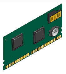
FIGURE 4-2 ALOM System Controller Card
The ALOM system controller card features serial and 10BASE-T Ethernet interfaces that provide multiple ALOM system controller software users with simultaneous access to the Sun Fire V445 server. ALOM system controller software users are provided secure password-protected access to the system's Solaris and OpenBoot console functions. ALOM system controller users also have full control over power-on self-test (POST) and OpenBoot Diagnostics tests.
| Note - The ALOM system controller serial management port (labeled SERIAL MGT) and network management port (labeled NET MGT) are present in the Solaris OS device tree as /dev/ttya, and in the OpenBoot configuration variables as ttya. However, the serial management port does not function as a standard serial connection. If you want to attach a standard serial device to the system (such as a printer), you need to use the DB-9 connector on the system back panel, which corresponds to /dev/ttyb in the Solaris device tree, and as ttyb in the OpenBoot configuration variables. See About the Serial Ports for more information. |
The ALOM system controller card runs independently of the host server, and operates off standby power from the server power supplies. The card features on-board devices that interface with the server environmental monitoring subsystem and can automatically alert administrators to system problems. Together, these features enable the ALOM system controller card and ALOM system controller software to serve as a lights out management tool that continues to function even when the server OS goes offline or when the server is powered off.
The ALOM system controller card plugs in to a dedicated slot on the motherboard and provides the following ports (as shown in FIGURE 4-3) through an opening in the system's back panel:
FIGURE 4-3 ALOM System Controller Card Ports
All system communication with storage, peripherals and network interface devices is mediated by four buses using three Peripheral Component Interconnect (PCI) bridge chips on the system motherboard. The Fire ASIC PCIe Northbrige manages communication between the system main interconnect bus (J-Bus) and two PCIe buses. In addition, two PCIe/PCI-X bridge ASICs manage communication from each PCIe bus to two PCI-X buses, giving the system a total of four PCI buses. The four PCI buses support up to four PCIe interface cards and four PCI-X interface cards, as well as multiple motherboard devices.
TABLE 4-2 describes the PCI bus characteristics and maps each bus to its associated bridge chip, integrated devices, and PCI card slots. All slots comply with PCI Local Bus Specification Revision 2.2.
| Note - PCI cards in a Sun Fire V445 server are not hot-pluggable or hot-swappable. |
|
PCIe Slot 6 x8 (wired x16)
|
|||
|
PCI-X Slot 4 64-bit 133MHz 3.3v *** |
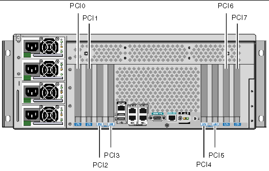
FIGURE 4-4 shows the PCI card slots on the motherboard.

TABLE 4-3 lists the device name and path for the eight PCI slots.
For information about installing or removing PCI cards, see the Sun Fire V445 Server Service Manual.
The Sun Fire V445 server supports 2 configurations for the SAS controller: the Standard configuration and the Alternate configuration. The Standard configuration embeddes the SAS controller logic on the motherboard. The Alternate configuration uses an intelligent, two-channel, SAS controller. This controller resides on PCI Bus 2B and supports a 64-bit, 66-MHz PCI interface.
Either configuration provides hardware RAID mirroring (RAID 0,1) capability with higher performance than conventional software RAID mirroring. Up to two pairs of hard disk drives can be mirrored using a SAS controller.
For more information about RAID configurations, see About RAID Technology. For more information about configuring hardware mirroring using the SAS controller, see Creating a Hardware Disk Mirror.
The Sun Fire V445 server includes a single SAS backplane with connections for up to eight internal hard disk drives, all of which are hot-pluggable.
The SAS disk backplane accepts eight, low-profile (2.5-inch), SAS disk drives. Each hard disk drive is connected to the backplane with a standard SAS hot-plug disk connector, which makes it easy to add or remove hard disk drives from the system. Disks using SCA connectors provide better serviceability than disks using other types of connectors.
For information about installing or removing a SAS backplane, refer to the Sun Fire V445 Server Service Manual.
For information about installing or removing the SAS backplane, refer to the Sun Fire V445 Server Service Manual.
In a Sun Fire V445 server, the SAS disk drives are hot-pluggable components. Hot-pluggable components you can install or remove while the system is running, without affecting system operation. However, you must prepare the OS prior to the hot-plug operation by performing certain system administration tasks.
The power supplies, fan trays, and USB components are hot-swappable. Hot-swappable components you can remove and replace without software preparation and without affecting system operation. No other components are hot-swappable.

|
Caution - You must always leave in place a minimum of two operational power supplies and one operational fan tray in each of the three fan tray pairs. |
Before performing hard disk drive hot-plug operations, use the Solaris cfgadm(1m) utility to prepare the OS. The cfgadm utility is a command-line tool for managing hot-plug operations on Sun Fire V445 internal disk drives and external storage arrays. Refer to the cfgadm man page.
For more information about the disk drives, see About the Internal Disk Drives. For general hard disk hot-plug procedures, refer to the Sun Fire V445 Server Service Manual. For procedures to perform a hard disk hot-plug operation on mirrored and nonmirrored disks, see Performing a Mirrored Disk Hot-Plug Operation and Performing a Nonmirrored Disk Hot-Plug Operation.

|
Caution - When hot-plugging a hard disk drive, first ensure that the drive's blue OK-to-Remove indicator is lit. Then, after disconnecting the drive from the SAS backplane, allow 30 seconds or so for the drive to spin down completely before removing it. Failing to let the drive spin down before removing it could damage the drive. See Chapter 6. |
Sun Fire V445 server power supplies are hot-swappable. A power supply is hot-swappable only when it is part of a redundant power configuration, which is a system configured with more than two power supplies in working condition.

|
Caution - Removing a supply that is one of only two installed could cause undefined behavior in the server and could lead to system shutdown. |
For additional information, see About the Power Supplies. For instructions on removing or installing power supplies, refer to the Sun Fire V445 Server Service Manual.
For procedues on removing and installing fan trays, refer to the Sun Fire V445 Server Service Manual.

|
Caution - At least one fan must remain operational in each of the three pairs of fan trays to maintain adequate system cooling. |
There are two USB ports located on the front panel and two on the back panel. For details on the supported components, see About the USB Ports.
The Sun Fire V445 server supports up to eight internal, hot-pluggable 2.5 inch SAS disk drives, attached to a backplane. The system also includes an internal SAS controller. See About the SAS Controller.
Indicators are associated with each drive, indicating the drive's operating status, hot-plug readiness, and any fault conditions associated with the drive.
FIGURE 4-5 shows the system's eight internal hard disk drives and highlights the series of indicators on each drive. Disk drives are numbered 0, 1, 2, 3, 4, 5, 6, and 7, with drive 0 being the default system disk.
FIGURE 4-5 Hard Disk Drives and Indicators
See TABLE 4-4 for a description of hard disk drive indicators and their function.
|
On - Drive is receiving power. Solidly lit ifdrive is idle. Flashes while the drive processes a command. |
| Note - If a hard disk drive is faulty, the system Service Required indicator is also lit. See Front Panel Indicators for more information. |
The hot-plug feature of the system's internal hard disk drives enables you to add, remove, or replace disks while the system continues to operate. This capability significantly reduces system downtime associated with hard disk drive replacement.
Disk drive hot-plug procedures require software commands for preparing the system prior to removing a hard disk drive and for reconfiguring the OS after installing a drive. For detailed instructions, see Chapter 6 and also the Sun Fire V445 Server Service Manual.
The Solaris Volume Manager software supplied as part of the Solaris OS allows you to use internal hard disk drives in four software RAID configurations: RAID 0 (striping), RAID 1 (mirroring), and RAID 0+1 (striping plus mirroring). You can also configure drives as hot-spares, disks installed and ready to operate if other disks fail. In addition, you can configure hardware mirroring using the system's SAS controller. For more information about all supported RAID configurations, see About RAID Technology. For more information about configuring hardware mirroring, see Creating a Hardware Disk Mirror.
The Power Distribution Board distributes DC power from four power supplies to all internal system components. The system's four power supplies called power supply 0, power supply 1, power supply 2 and power supply 3 plug in directly to connectors on the power distribution board. Each power supply has a separate AC inlet. Two independent AC power sources should be used to provide redundant AC inlet power. All four power supplies share equally in satisfying the power demands of the system - any two of which can satisfy the entire load of a system with a maximum configuration. AC power is brought to each power supply with a power cord (total of four power cords).
The Sun Fire V445 server's power supplies are modular, hot-swappable units. They are customer replacable units (CRUs) designed for fast, easy installation or removal, even while the system is fully operational. Power supplies are installed in bays at the rear of the system.
The power supplies operate over an AC input range of 100 240 VAC, 47-63 Hz. Each power supply can provide up to 550 watts of 12V DC power. Each power supply contains a series of status indicators, visible when looking at the back panel of the system. FIGURE 4-6 shows the location of the power supplies and indicators.
FIGURE 4-6 Power Supplies and Indicators
See TABLE 4-5 for a description of power supply indicators and their function, listed from top to bottom.
| Note - If a power supply is faulty, the system Service Required indicator is also lit. See Front Panel Indicators for more information. |
Power supplies in a redundant configuration feature a hot-swap capability. You can remove and replace a faulty power supply without shutting down the OS or turning off the system power.
A power supply can be hot-swapped only when there are at least two other power supplies online and working properly. In addition, the cooling fans in each power supply are designed to operate independently of the power supplies. If a power supply fails, but its fans are still operable, the fans continue to operate by drawing power from the other power supply through the power distribution board.
For additional details, see About Hot-Pluggable and Hot-Swappable Components. For information about removing and installing power supplies, see Performing a Power Supply Hot-Swap Operation, and refer to your Sun Fire V445 Server Service Manual.
You can hot-swap any power supply while two others are installed, online, and operational. Check the Service Required indicators to verify which power supply has failed. The failed power supply causes the amber system Service Required indicator and power supply Service Required indicator to light.
To complete this procedure, refer to the Sun Fire V445 Server Service Manual.
The system is equipped with six fan trays organized into three redundant pairs. One redundant pair is for cooling the disk drives. The other two redundant pairs are for cooling the CPU/Memory modules, memory DIMMs, I/O subsystem, and provide front-to-rear cooling of the system. Not all fans must be present to provide adequate cooling - only one fan per redundant pair must be present.
| Note - All system cooling is provided by the fan trays - power supply fans do not provide system cooling. |
The fans in the system plug directly into the motherboard. Each fan is mounted on its own tray and is individually hot-swappable. If either fan in a pair fails the remaining fan is adequate to keep its portion of the system cool. The presence and health of the fans are indicated through six bicolor indicators located on the SAS backplane.
Open the fan tray doors on the top cover of the server to access the system fans. Power supplies are cooled separately, each power supply with its own internal fan.

|
Caution - Fan trays contain sharp moving parts. Use extreme caution when servicing fan trays and blowers. |
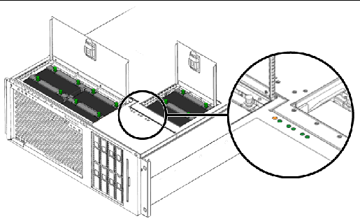
FIGURE 4-7 shows all six system fan trays and their corresponding indicators. For each fan in the system, the environmental monitoring subsystem monitors fan speed in revolutions per minute.

FIGURE 4-7 System Fan Trays and Fan Indicators
Refer to these indicators to determine which fan tray needs to be replaced.
TABLE 4-6 provides a description of the fan tray indicators.
| Note - If a fan tray is not present, its corresponding indicator is not lit. |
| Note - If a fan tray is faulty, the system Service Required indicator is also lit. See Front Panel Indicators for more information. |
The environmental subsystem monitors all fans in the system, and prints a warning and lights the system Service Required indicator if any fan falls below its nominal operating speed. This provides an early warning to an impending fan failure, enabling you to schedule downtime for replacement before an overtemperature condition shuts down the system unexpectedly.
For a fan failure, the following indicators are lit:
In addition, the environmental subsystem prints a warning and lights the system Service Required indicator if internal temperature rises above a predetermined threshold, either due to fan failure or external environmental conditions. For additional details, see Chapter 8.
The minimum system configuration requires at least one fan operating per redundant pair.
| Note - For instructions on how to remove and install fan trays, refer to the Sun Fire V445 Server Service Manual. |
The system front and back panels provide two external Universal Serial Bus (USB) ports on two independent controllers to connect USB peripheral devices such as:
The USB ports are compliant with the Open Host Controller Interface (Open HCI) specification for USB Revision 1.1 and also 2.0 compliant (EHCI) and capable of 480 Mbps as well as 12 Mbps and 1.5 Mbps. The ports support isochronous and asynchronous modes, and enable data transmission at speeds of 1.5 Mbps and 12 Mbps. Note that the USB data transmission speed is significantly faster than that of the standard serial ports, which operate at a maximum rate of 460.8 Kbaud.
The USB ports are accessible by connecting a USB cable to a back panel USB connector. The connectors at each end of a USB cable are keyed so that you cannot connect them incorrectly. One connector plugs in to the system or USB hub. The other connector plugs in to the peripheral device. Up to 126 USB devices can be connected to each controller simultaneously, through the use of USB hubs. The USB ports provide power for smaller USB devices such as modems. Larger USB devices, such as scanners, require their own power source.
For the USB port locations, see Locating Back Panel Features and Locating Front Panel Features. Also see Reference for the USB Connectors.
The default console connection to the Sun Fire V445 server is through the RJ-45 serial management port (labeled SERIAL MGT) on the back panel of the ALOM system controller card. This port operates only at 9600 baud.
| Note - The serial management port is not a standard serial port. For a standard and POSIX compliant serial port, use the DB-9 port on the system back panel, which corresponds to TTYB. |
The system also provides a standard serial communication port through a DB-9 port (labeled TTYB) located on the back panel.This port corresponds to TTYB, and supports baud rates of 50, 75, 110, 134, 150, 200, 300, 600, 1200, 1800, 2400, 4800, 9600, 19200, 38400, 57600, 115200, 153600, 230400, 307200, and 460800. The port is accessible by connecting a serial cable to the back panel serial port connector.
For the serial port location, see Locating Back Panel Features. Also see Reference for the Serial Port Connector. For more information about the serial management port, see Chapter 2.
Copyright © 2007, Sun Microsystems, Inc. All Rights Reserved.