| C H A P T E R 2 |
|
Installing the Server in a Rack |
This chapter describes how to install the Sun Fire V60x and Sun Fire V65x servers in a rack, using a four-post, two-post, or front-mount rack server. This chapter contains the following sections:
Before installing the Sun Fire V60x and Sun Fire V65x servers, it is best to decide where you want to configure them:
If you are going to configure the server after it is mounted in the rack, proceed to the section titled Precautions. To configure the Sun Fire V60x and Sun Fire V65x servers while they are in the rack, it is best to use a laptop to connect to the server Emergency Management Port (EMP) on the rear panel of the server. See Configuring an External Serial Console for details on hooking up the laptop to the EMP.
If you are going to configure the server in a lab environment before it is installed in a rack, proceed to Chapter 3, "Powering On and Configuring the Server," then return to the section in this chapter titled Precautions.
|
Note - The preferred method is to configure the server on a lab bench, as all of the server components are much more accessible. |
Before beginning the rack installation process, read through the following precautions.
The equipment rack must be anchored to an unmovable support to prevent it from falling over when one or more servers are extended in front of it on slide assemblies. The equipment rack must be installed according to the manufacturer's instructions. You must also consider the weight of any other device installed in the rack.
You are responsible for installing an AC power disconnect for the entire rack unit. This main disconnect must be readily accessible, and it must be labeled as controlling power to the entire unit, not just to the server(s).
3. Grounding the Rack Installation
To avoid a potential electrical shock hazard, you must include a third wire safety grounding conductor with the rack installation. If server power cords are plugged into AC outlets that are part of the rack, you must provide proper grounding for the rack itself. If server power cords are plugged into wall AC outlets, the safety grounding conductor in each power cord provides proper grounding only for the server. You must provide additional, proper grounding for the rack and other devices installed in it.
The ambient operating temperature of the server, when installed in an equipment rack, must not go below 5 °C (41 °F) or rise above 35 °C (95 °F). Extreme fluctuations in temperature can cause a variety of problems in your server.
The equipment rack must provide sufficient airflow to the front of the server to maintain proper cooling. It must also include ventilation sufficient to exhaust a maximum of 950 BTUs per hour for fully loaded Sun Fire V60x and Sun Fire V65x servers.
It is important to note that this is the maximum, and a minimum or typical system could be much less. You may want to calculate the BTU/hr more accurately for your configuration. An extra 500 BTUs per hour over many systems would translate into a large error when calculating air-conditioning capacity.
There are two methods for installing the Sun Fire V60x and Sun Fire V65x servers in a rack:
This mounting method is quick and easy, but makes it somewhat difficult to service the server.
There are three mounting methods using the bracket kit:
Four-post mounting is the recommended method. It the most stable and sturdy method. The mid-mount system requires only two posts, but the posts must be adequately strong and stable to support the weight of multiple servers. The front mount method is highly discouraged, as most racks are unable to safely and reliably support the entire weight of a server through the front rack posts.
This mounting method is more complicated, but allows the server to be more easily serviced.
1. Use the fingerhole on the left side of the bezel to pull the bezel out.
2. Pull out the left side first, allowing the right side to rotate in the chassis handle until it comes loose.
1. Snap the right side of the bezel into the right chassis handle.
2. Swing the left side of the bezel in, allowing the right side to rotate in the chassis handle.
3. Gently push the left side of the bezel into the left hand chassis handle until it snaps into place.
The bracket kit allows you to install the server chassis into most two- and four-post (open-frame) rack and EIA-310D compliant enclosed cabinets, as well as a
Sun Rack 900.
The bracket kit, included as standard equipment with the server, includes the following items:
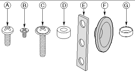
a. Screw, #10-32 x 1/2-inch--qty. 8 (Sun Rack 900: M6 x 12mm)
b. Screw, #6-32 x 3/16-inch--qty. 4
c. Screw, #10-32 x 7/8-inch--qty. 2 (Sun Rack 900: M6 x 20mm)
The sections that follow give instructions for mounting the Sun Fire V60x and Sun Fire V65x servers in a four-post rack system. This is the most stable and secure mounting method.
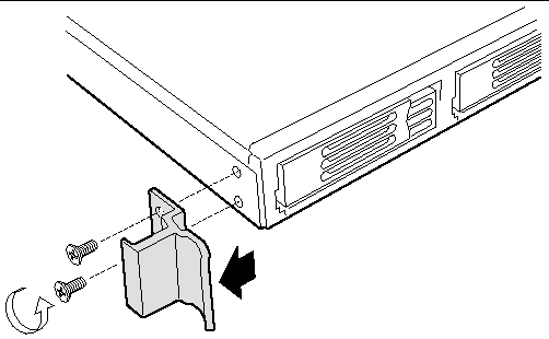
2. Remove two screws (FIGURE 2-2) from each handle.
3. Set the handles and screws aside for reattachment later.
1. Place a chassis bracket along one side of the chassis in the front-mount position (FIGURE 2-3, A).
2. Align the holes (B) in the bracket with the tabs (C) on the chassis and place the bracket against the chassis.
3. Slide the bracket as far as it will go toward the front of the chassis.
4. Fasten the bracket to the chassis using screw (D).
5. In the same manner, attach a chassis bracket to the other side of the chassis.
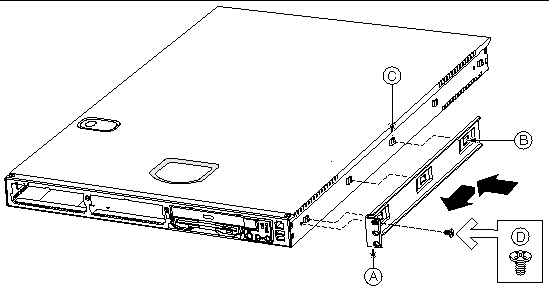
a. Chassis bracket in front-mount position
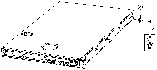
1. Place a chassis disk at the side of the chassis towards the rear (see FIGURE 2-4, A).
2. Install screw (B) and tighten.
3. In the same manner, attach a chassis disk to the opposite side of the chassis.
 [ D ]
[ D ]
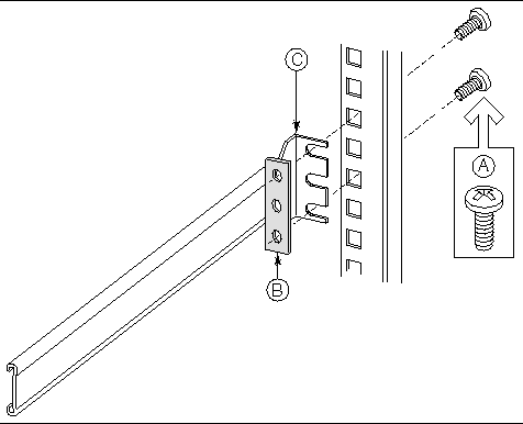
1. Attach a nut bar (FIGURE 2-5, B) on the inside of the two rear rack posts using screws (A). Do not completely tighten the screws--leave them loose enough to allow insertion of the brackets in step 2.
2. Insert the slotted foot of a rear bracket (C) between each nut bar and post.
3. Align the face of the bracket foot with the edge of the rack post and firmly tighten the screws.
a. #10-32 x 1/2-inch screw with washers (Sun Rack 900: M6 x 12mm)
1. With the chassis front facing you, lift the chassis and position the chassis disks (FIGURE 2-6, A) so they fit in the rear brackets (B).
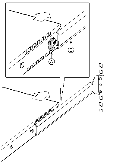
2. Slide the chassis toward the rear of the rack until the front of the chassis brackets contact the front posts.
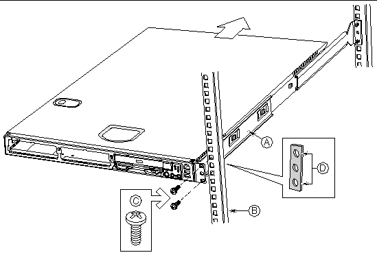
3. Attach the chassis brackets (FIGURE 2-7, A) to the front posts (B) using two screws (C) and one nut bar (D) per side.
 [ D ]
[ D ]
c. #10-32 x 1/2-inch screw with washers (Sun Rack 900: M6 x 12mm)
d. Nut bar (not required for Sun Rack 900)
|
Note - The handles are required to hold the bezel on. If you will not be installing a bezel, you do not need to install the handles. |
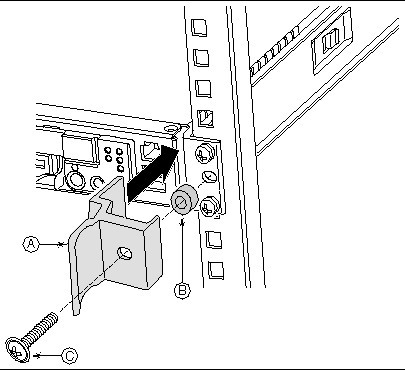
1. Slide a handle (FIGURE 2-8, A) between the chassis and the chassis bracket.
2. Align the hole in the handle with the unused hole in the chassis bracket.
3. Install a spacer (B) between the handle and the chassis bracket.
4. Install and tighten screw (C) to secure the handle.
5. In the same manner, attach the other handle to the opposite side.
You have completed the installation of your chassis in a four-post rack system
 [ D ]
[ D ]
c. #10-32 x 7/8-inch screw with washer (Sun Rack 900: M6 x 20mm)
The sections that follow give instructions for mid-mounting the Sun Fire V60x and Sun Fire V65x servers in a two post rack system. This method is acceptable, but it is not as secure as the four-post mounting system.
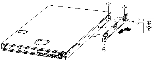
1. Place a mounting bracket (FIGURE 2-9, A) along one side of the chassis in the
mid-mount position.
2. Align the holes (B) in the bracket with the tabs (C) on the chassis and place the bracket against the chassis.
3. Slide the bracket as far as it will go toward the front of the chassis.
4. Fasten the bracket to the chassis using screw (D).
5. In the same manner, attach a bracket to the other side of the chassis.
 [ D ]
[ D ]
a. Chassis bracket in mid-mount position
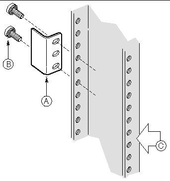
1. Position a supplied L bracket (FIGURE 2-10, A) on the backside of the center post (C).
2. Attach the L bracket to the center post using the screws (B) supplied with your rack. Do not fully tighten at this time.
3. In the same manner, attach an L bracket to the other center post.
 [ D ]
[ D ]
b. Screw (supplied by your rack manufacturer)
c. Front side of typical right center post
1. Locate one person at the front of the rack and one at the rear.
2. Position the chassis so that the L brackets (FIGURE 2-11, A) are inserted into the chassis mounting brackets (B).
3. While supporting the weight of the chassis, adjust the L brackets to fit tightly into the chassis brackets (C).
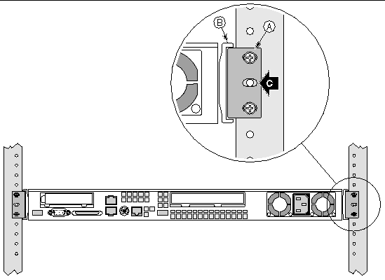
4. Slide the chassis toward the rear of the rack until the front of the chassis mounting brackets contact the front of the center posts.
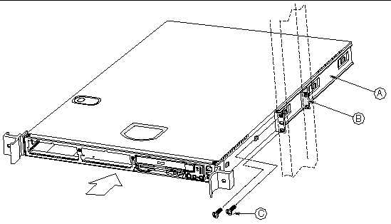
5. Using the screws (FIGURE 2-12, C) supplied with your rack, attach the front of the mounting brackets to the front of the center posts.
You have completed the mid-mount installation of your chassis in a two-post rack system.
 [ D ]
[ D ]
a. Chassis bracket in mid-mount position
c. Screw (supplied by rack manufacturer)
This section gives instructions for front mounting the Sun Fire V60x and Sun Fire V65x servers in a two-post rack system.
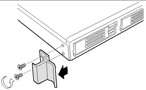
2. Remove two screws from each handle (see FIGURE 2-13).
3. Set the handles and screws aside for reattachment later.
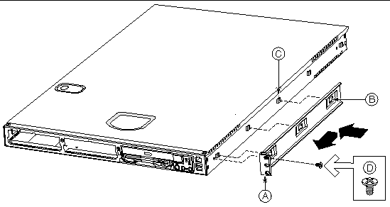
4. Place a mounting bracket (FIGURE 2-14, A) along one side of the chassis in the front-mount position.
5. Align the holes (B) in the bracket with the tabs (C) on the chassis and place the bracket against the chassis.
6. Slide the bracket as far as it will go toward the front of the chassis.
7. Attach the bracket to the chassis using screw (D).
8. In the same manner, attach a bracket to the other side of the chassis.
 [ D ]
[ D ]
a. Chassis bracket in front-mount position
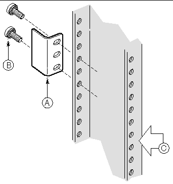
1. Position an L bracket (FIGURE 2-15, A) on the backside of the front post (C).
2. Attach the L bracket to the front post using the screws (B) supplied with your rack. Do not fully tighten at this time.
3. In the same manner, attach an L bracket to the other front post.
 [ D ]
[ D ]
b. Screw (supplied by rack manufacturer)
c. Front flange of typical right front post
1. Locate one person at the front of the rack and one at the rear.
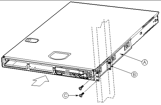
2. Position the chassis so that the L brackets (FIGURE 2-16, A) are inserted into the chassis mounting brackets (B).
3. While supporting the weight of the chassis, adjust the L brackets to fit tightly into the chassis brackets (C).
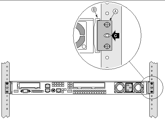
4. Slide the chassis toward the rear of the rack until the front of the chassis brackets contact the front of the front posts.
5. Using the fasteners (FIGURE 2-17, C) supplied with your rack, attach the front of the mounting brackets to the front of the front posts.
 [ D ]
[ D ]
a. Chassis bracket in front-mount position
c. Screw (supplied by rack manufacturer)
|
Note - The handles are only required to hold the bezel on. If you will not be installing a bezel, you do not need to install the handles. |
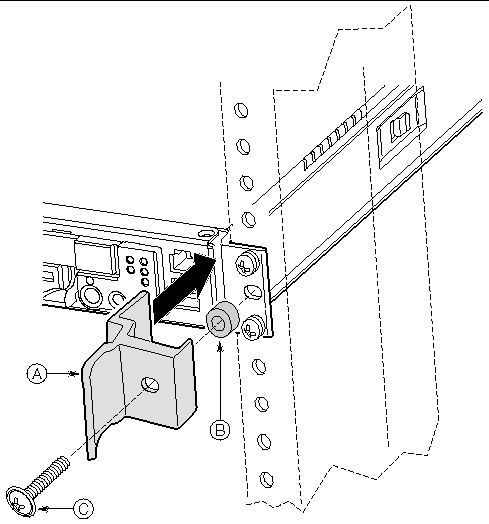
1. Slide a handle (FIGURE 2-18, A) between the chassis and the chassis bracket.
2. Align the hole in the handle with the unused hole in the chassis bracket.
3. Install a spacer (B) between the handle and the bracket.
4. Install and tighten screw (C) to secure the handle.
5. In the same manner, attach the other handle to the opposite side.
 [ D ]
[ D ]
c. #10-32 x 7/8-inch screw with washer
The rail kit is an extra cost option, and allows you to install the Sun Fire V60x and Sun Fire V65x servers in most four-post rack cabinet systems, Sun Rack 900, and Sun StorEdge racks.
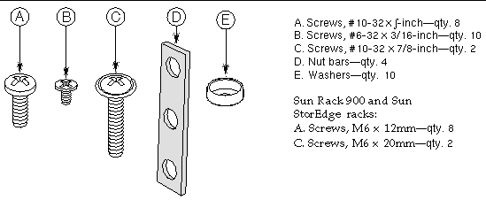
The slide rail kit, available as optional equipment, includes the following items:
 [ D ]
[ D ]
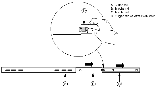
1. Fully extend a rail assembly (FIGURE 2-20). The finger tab (D) for the extension lock is revealed.
2. Press the finger tab and slide the inside rail (C) from the middle rail (B) until it completely separates.
|
Note - The middle rail (B) and outer rail (A) cannot be separated. |
 [ D ]
[ D ]
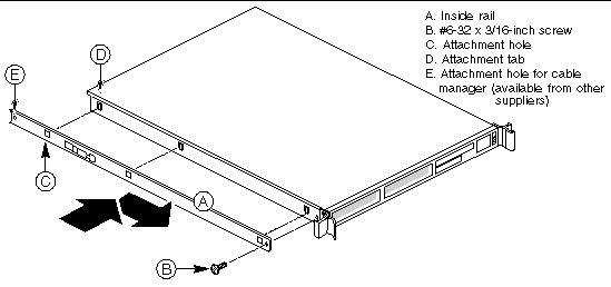
1. Position an inside rail (FIGURE 2-21, A) along one side of the chassis with the finger tab facing outward and located closer to the rear of the chassis.
2. Align the holes (C) in the rail with the tabs (D) on the chassis and place the rail against the chassis.
3. Slide the rail as far as it will go toward the front of the chassis to engage the tabs.
4. Fasten the rail to the chassis using one screw (B) at the front of the chassis.
5. In the same manner, attach the other inside rail to the other side of the chassis.
 [ D ]
[ D ]
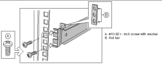
1. Using two screws (FIGURE 2-22, A) with washers, attach one nut bar (B) to the inside of the rack post. Do not completely tighten the screws--leave them loose enough to allow insertion of the brackets in the next step.
2. Insert the slotted foot of a rail bracket between each nut bar and post.
3. Align the face of the bracket foot with the inside edge of the rack post and firmly tighten the screws.
4. Repeat steps 1 to 3 above to install the other 3 brackets (2 Front and 2 Back total). Ensure all brackets are at the same height on the rack.
 [ D ]
[ D ]
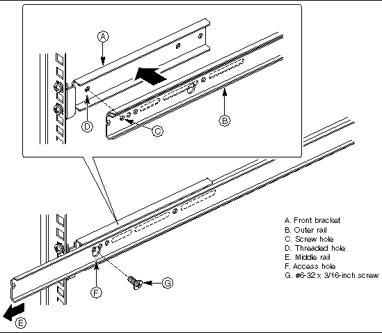
1. Position a rail assembly (middle and outer rails) with its black plastic end caps toward the rear of the rack and its outer rail closest to the brackets.
2. Align the front screw hole (FIGURE 2-23, C) in the outer rail (B) with the threaded hole (D) nearest the front of the front bracket (A) and fit the rail assembly into the front and rear brackets.
3. Slide the middle rail toward the front (E) until the access hole (F) in the middle rail is aligned with the front screw hole (C) in the outer rail.
4. Insert screw (G) through the access hole and loosely attach the outer rail to the front bracket.
5. In a similar manner to steps 2 through 4, install a screw through a slot in the outer rail and into the rear-most threaded hole in the front bracket. Firmly tighten this screw.
6. Firmly tighten the front screw (G) installed loosely in step 4.
7. In the same manner, attach the other rail assembly to the other side.
 [ D ]
[ D ]
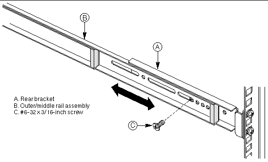
1. Slide the middle rail toward the front (FIGURE 2-24) until the rear bracket area is accessible.
2. Attach the rear end of the outer rail (B) to the rear bracket (A) with at least one screw (C). If possible, attach at two places.
3. In the same manner, attach the other rail assembly to the other side.
 [ D ]
[ D ]
1. Fully extend the left and right rails (FIGURE 2-25) until the extension locks have engaged and the rails will not push back in. The rail system is now ready to receive the chassis.
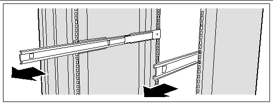
2. With the chassis front facing you, lift the chassis and carefully insert the rails attached to the chassis in the extended rails.
3. Slide the chassis toward the rear of the cabinet until the rails lock together.
4. Depress and hold down the finger tabs (FIGURE 2-26, A) on both extension locks while sliding the chassis toward the rear.
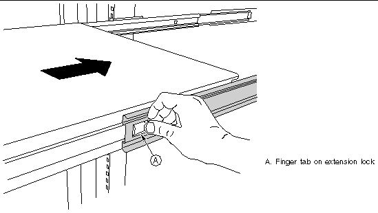
5. Slide the chassis all the way into the rack until the chassis handles are against the front posts.
The Sun Fire V60x and Sun Fire V65x servers have a number of connectors. Some are on the front panel; others are located on the rear panel. This section summarizes the usage of each connector.
To access the front panel connectors when a front bezel is installed, grasp the bezel on the left side at the finger hole and gently pull it towards you, unhinging it at the right until it unsnaps from the chassis. FIGURE 2-27 shows the front of each of the servers with the bezels removed.
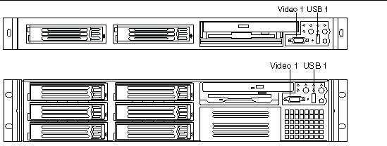
There are two connectors on the front panel (see FIGURE 2-27):
The USB 1 connector provides industry-standard USB v1.1 functionality. The industry-standard USB v1.1 specification defines the pin configuration and operation of this interface. The USB connector pinout is shown in TABLE 2-1.
|
Note - The USB port is disabled until an OS and the USB drivers are installed. A PS/2 type keyboard and/or mouse may be required for initial bootup and configuration. |
The DB15 video 1 connector located on the front panel is designed to access the video of the system from the front panel of the system. Both the front and rear video ports share the same video signals. By default, the rear video 2 port is enabled when there is no monitor connected to the front video port. However, when a monitor is connected to the front video 1 port, logic on the main board disables the rear video 2 port and directs the video signal to the monitor connected to the front panel. If a video controller board is plugged into an internal PCI riser board slot, the video to both front and rear panel connectors is disabled. The video 1 connector pinout is shown in TABLE 2-2.
FIGURE 2-28 shows the rear panels of the each of the servers
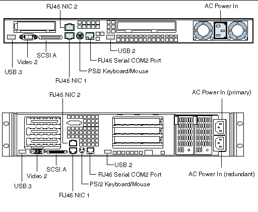
The following connectors are located on the rear panel:
The server provides two 10BASE-T/100BASE-TX/1000BASE-TX Network Interface Controllers (NICs). The NICs support the following features:
This connector is where you plug in the AC power cord (a power cord is supplied appropriate to your geographic region).
|
Note - On the Sun Fire V65x server, as viewed from the rear, the top AC power connector serves the power supply on the left and the AC power connector on the bottom serves the power supply on the right. In a server with a single supply, the AC cord must be plugged into the upper AC connector. In a server with redundant power supplies, you must plug in two AC power cords[1]. |
The use of RJ-45 connectors for the serial interface is widely becoming a standard for use in the high-density server market.
The BIOS can be set to redirect BIOS, bootup, and OS messages to the COM2 serial port (see Configuring an External Serial Console for details). The default communications settings for the serial console port on the server are:
The intended use for the rear panel RJ-45 serial COM2 port is for remote EMP communication, which is accomplished when the port is connected to a serial terminal concentrator. With the optional RJ-45 to DB9 Serial Adapter Kit, the serial port can also be configured for use with a modem. Replaceable Components gives ordering information for the adapter kit. The rear COM2 serial port is traditionally referred to as COM2 (DOS, Windows), ttyS1 (Linux), or ttyb (Solaris).
Serial terminal concentrators use one of two serial communication standards. Some terminal concentrators require a Data Carrier Detect (DCD) signal, while others require a Data Set Ready (DSR) signal. The server Main Board can be configured to support either of these configurations by setting the jumper appropriately on the jumper block, located directly behind the RJ-45 serial connector on the Main Board.
The rear RJ-45 serial COM2 port can support any standard serial device. An RJ-45 connector was selected to allow for direct support for serial port concentrators, which typically use RJ-45 connectors and are widely used in the high-density server market to access the server management features of the server.
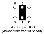
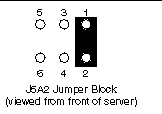
To give support for either of two serial configuration standards used by serial port concentrators, the J5A2 jumper block, located on the Main Board inside the server directly behind the rear RJ-45 serial port, must be jumpered appropriately according to which standard is desired.
For serial devices that require a DSR signal (default), the J5A2 jumper block must be configured as follows: place the jumper across positions 3 and 4 (the two middle jumper posts) as shown in FIGURE 2-29.
For serial devices that require a DCD signal, the J5A2 jumper block must be configured as follows: place the jumper across positions 1 and 2 as shown in FIGURE 2-30.
For those serial devices that require a DB9 type of serial connector, an 8-pin RJ-45-to-DB9 adapter must be used. TABLE 2-3 provides the pinout required for the adapter to provide RS232 support.
|
1 or 6[2] |
|||
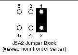
As an example, when using an external modem to access the server management features of the server Main Board, you must first set the J5A2 jumper to support a DCD signal and make or choose the appropriate RJ-45-to-DB9 adapter.
If you choose to develop your own RJ-45-to-DB9 adapter, see TABLE 2-3 for the appropriate pinout configuration.
The USB 1 connector on the front panel, and the USB 2 and USB 3 connectors on the rear panel provide USB v1.1 functionality. All ports function with identical capabilities and with the same bandwidth. The industry-standard USB v1.1 specification defines the external connectors.
|
Note - The USB port is disabled until an OS and the USB drivers are installed. A PS/2 type keyboard and/or mouse may be required for initial bootup and configuration. |
A single PS/2 port located on the back panel is provided to support a standard keyboard or mouse. A PS/2 Y-cable adapter, included with the Sun Fire V60x and Sun Fire V65x servers, allows simultaneous use of the PS/2 keyboard and mouse. Such cable adapters are also commonly available at most computer stores.
|
Note - The USB port is disabled until an OS and the USB drivers are installed. A PS/2 type keyboard and/or mouse may be required for initial bootup and configuration. |
The Sun Fire V60x and Sun Fire V65x servers include an onboard Adaptec dual channel Ultra-320 SCSI controller capable of controlling up to three internally mounted SCSI drives (for the Sun Fire V60x server), up to six internally mounted SCSI drives (for the Sun Fire V65x server), and up to 15 external SCSI drives. The controller is capable of operations using either 16-bit Single-Ended (SE) or Low-Voltage Differential (LVD) SCSI providing transfer rates of 40 MBps (Ultra-wide SE), 80 MBps (Ultra 2), 160 MBps (Ultra 160/m) or 320 MBps (Ultra 320/m). The onboard SCSI controller is connected to a SCSI backplane board inside the server using a
68-pin SCSI cable. The SCSI backplane provides connections for up to three (Sun Fire V60x server) or six (Sun Fire V65x server) internally mounted SCA LVDS SCSI drives with standard 80-pin SCA connectors. Channel B is used exclusively by internal drives while channel A is used for connecting to external SCSI devices by means of a rear panel high-density SCSI connector. The connector supports a standard high-density 68-pin connector. Use only shielded Ultra-160 LVDS rated cables for connection to external SCSI drives.
Video is provided by default to the rear panel DB15 connector. When a monitor is plugged into the front panel DB15 video connector, video is routed to the front panel connector and the rear connector is disabled. This can be done by "hot plugging" the video connector while the system is still running. If a video controller board is plugged into an internal PCI riser board slot, the video to both front and rear panel connectors is disabled. The video 2 connector pinout is shown in FIGURE 2-4.
The Sun Fire V60x and Sun Fire V65x servers provide an ATI Rage XL PCI graphics accelerator, along with 8 MB of video SDRAM and support circuitry for an embedded SVGA video subsystem. The SVGA subsystem supports a variety of modes, up to 1600 x 1200 resolution in 8/16/24/32 bpp modes under 2D, and up to 1024 x 768 resolution in 8/16/24/32 bpp modes under 3D. It also supports both CRT and LCD monitors with up to 100 Hz vertical refresh rates. All of these capabilities depend on software support.
The server provides a standard 15-pin VGA connector and supports disabling of the on-board video through the BIOS Setup menu or when a plug-in video card is installed in any of the PCI riser board slots.
Copyright © 2003, Sun Microsystems, Inc. All rights reserved.