| C H A P T E R 3 |
|
Controls and Indicators |
This chapter describes the control pushbuttons and LED indicators on the Sun Fire V60x and Sun Fire V65x servers. All of the descriptions in this chapter pertain to buttons and indicators that are usable and visible from the outside of the chassis. For information about the controls and indicators on the server Main Board, see the additional information contained in Chapter 6.
The pushbuttons and LEDs on the front and rear panels are described in the following sections:
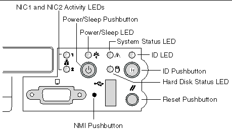
The front panel contains the pushbuttons and LEDs shown in FIGURE 3-1. Note that the illustration has the bezel removed.
 [ D ]
[ D ]
The front panel LEDs are summarized in TABLE 3-1.
|
This LED is controlled by software. It is steady on when the server is powered up. It is off when the system is off or in sleep mode. |
||
|
These LEDs are on when a good network link has been established. They blink green to reflect network data activity. |
||
|
This LED can assume different states (green, amber, steady, blinking) to indicate normal, degraded, non-critical fault, or critical fault server operation. Steady green: Indicates the system is operating normally Blinking green: Indicates the system is operating in a degraded condition. Blinking amber: Indicates the system is in a non-critical condition. Steady amber: Indicates the system is in a critical or non-recoverable condition. Off: Indicates POST/system stop. See Front-Panel System Status LED for more details regarding this LED. |
||
|
The Drive Activity LED on the front panel is used to indicate drive activity from the onboard SCSI controller. The server Main Board also provides a header, giving access to this LED for add-in IDE or SCSI controllers. Blinking green (random): Hard disk activity Off: No disk activity nor fault condition (or power is off). |
||
|
The blue System Identification LED is used to help identify a system for servicing when it is installed within a high density rack or cabinet that is populated with several other similar systems. The System ID LED is illuminated when the system ID button, located on the front panel, is pressed. If activated by the front panel pushbutton, the LED remains on until the pushbutton is depressed again. The LED also illuminates when the server receives a remote System Identify command from a remote management console. In this case, the LED turns off after a timeout period. An additional blue System ID LED on the Main Board is visible through the rear panel. It mirrors the operation of the front panel LED. |
The front panel pushbuttons are summarized in TABLE 3-2.
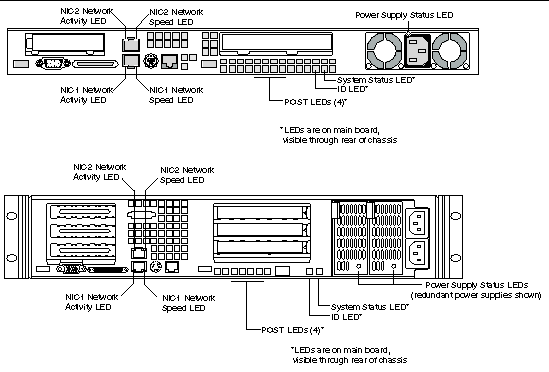
The rear panel contains the LEDs shown in FIGURE 3-2.
 [ D ]
[ D ]
|
This LED is on the left side of each NIC connector. |
||
|
To help diagnose power-on self test (POST) failures, a set of four bi-color diagnostic LEDs is located on the back edge of the server Main Board. These LEDs are visible through holes in the rear panel. Each of the four LEDs can have one of four states: Off, Green, Red, or Amber. For detailed information on these LEDs, see POST LED Indicators. |
||
|
This LED is located on the Main Board and is visible through holes in the rear panel. It can provide a mechanism for identifying one system out of a group of identical systems. This can be particularly useful if the server is used in a rack-mount chassis in a high-density, multiple-system application. The LED is activated by depressing the front panel System ID pushbutton or if the server receives a remote System Identify command from a remote management console. If activated by the front panel pushbutton, the LED remains on until the pushbutton is depressed again. When the LED illuminates due to a remote System Identify command, the LED turns off after a timeout period. An additional blue System ID LED is located on the front panel that mirrors the operation of the rear Main Board LED. |
||
|
This LED reflects the state of the System Status LED on the front panel. |
||
|
This is a bi-color LED that can be on, off, green, amber, or blinking, or a combination thereof. See Rear Panel Power Supply Status LED for more detailed information. |
Copyright © 2003, Sun Microsystems, Inc. All rights reserved.