| Solstice Enterprise Manager 4.1 Management Information Server (MIS) Guide |
Accessing a Remote MIS
This chapter provides instructions for accessing a remote Management Information Server (MIS). This chapter includes information about implementing a multiple-MIS architecture. Communication from one MIS to another allows you to view managed objects in a remote MIS as if they existed in your local MIS.
This chapter describes the following topics:
- Section 3.1 Implementing a Multiple-MIS Architecture
- Section 3.2 Comparing MIS-to-MIS Examples
- Section 3.3 Establishing MIS Connections
- Section 3.4 Sharing Data Between Connected MISs
- Section 3.5 Re-establishing a Remote MIS Link
3.1 Implementing a Multiple-MIS Architecture
To manage multiple network resources and increase system availability, you may want to distribute management information, control, and authority over multiple MISs. In a multiple-MIS architecture, the following apply:
- Network traffic and processing can be distributed between MISs.
- In an environment where two or more MISs need to transfer information or act on behalf of each other, one MIS takes on a manager role and the other can act in the agent role. Other MISs route information through the managing MIS.
- Users and applications access and act on consistent management information, without regard to location.
- All information is gathered via management requests to MIS. (There is no explicit MIS-to-MIS interface.)
- Any MIS can locate requested managed information and execute requests, thereby distributing the processing load.
Using a multiple-MIS architecture is referred to as MIS-to-MIS communication. MIS-to-MIS communication occurs when two or more MISs are connected and configured to forward requests for managed objects while performing the tasks of agent and manager.
MIS forwarding a request is acting in the manager role, while MIS receiving the request is acting in the agent role. To an application, it is transparent whether the object accessed is local or non-local.
MIS-to-MIS communication is analogous to NFS mounting a file system. Configuring a branch of the MIT for MIS-to-MIS communication is often referred to as mounting a section of the MIT.
In a management system such as an MIS, a service is provided to a predetermined set of managed objects in the MIT. Because objects for which MIS provides services are a subset of objects in the global name space, MIS must be able to act in both a manager and agent role. The division of roles is determined by the configuration of MIS and the requirements of the management framework. Refer to FIGURE 3-1 and FIGURE 3-2 for examples of MIS-to-MIS configurations.
3.2 Comparing MIS-to-MIS Examples
If you are thinking about implementing a multiple-MIS architecture for network management, use this section to compare examples of MIS-to-MIS communication with your MIS and network requirements. This information may help you decide whether to connect multiple-MISs.
3.2.1 Accessing Objects Without an MIS-to-MIS Connection
Refer to the following figure for an example of the MIT for two MISs, called A and B, which are not connected. You might choose a configuration of this type if Sys=A and Sys=B must remain unknown to each other.
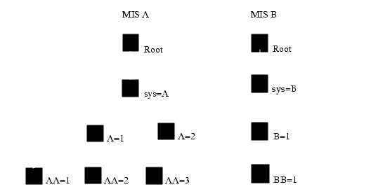
FIGURE 3-1 Two Unconnected MISsIf an application needs to be aware of multiple MISs, the awareness should come from an MIS-to-MIS connection. For example, if Alarm Manager needs to display logs from MIS A and MIS B, an MIS-to-MIS connection will enable doing that. There are several applications in EM that are multi-MIS aware. There can be one association between an MIS-to-MIS connection.
3.2.2 Accessing Managed Objects With an MIS-to-MIS Connection
Refer to the following figure for an example of the same two MISs from FIGURE 3-1 which are now connected, with MIS A acting in the manager role and MIS B acting in the agent role.
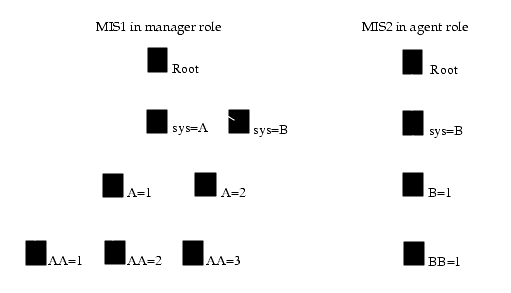
FIGURE 3-2 MITs of Two Connected MISsWhen an application connected to MIS A accesses any managed object with the first RDN equal to /sys=B, such as the managed object /sys=B/B=1 /BB=1, the request is forwarded by MIS A to MIS B.
The first Relative Distinguished Name (RDN) in the DN is used to decide if the request is local or remote. If the object /sys=A/A=2 is accessed, MIS A acts in the agent role and returns the local object. Actually, the Remote versus Local lookup is based on a special Fully Distinguished Name (FDN) table stored in MIS, which contains the FDNs of all "remote" trees.
To the application, access to the object on MIS A or MIS B is transparent. It is only aware that it has retrieved two objects with DNs. MIS, based on the first RDN of the requested DN, determines where the object actually resides.
It is possible for MIS B to mount MIS A so that whether the application is connected to MIS A or MIS B, the application accesses the same objects.
The example in FIGURE 3-2 presents a very simple and effective use of MIS-to-MIS communication. This hierarchical management scheme allows you to configure network management in an organized fashion.
In the following examples, suppose a company has a building with three physical networks:
- One system administrator (SA1) is responsible for the overall configuration.
- Another system administrator (SA2) is responsible for all the networks in the building.
- A third system administrator (SA3) is responsible for each individual net.
Assuming that each following box represents either an MIS or a system administrator, you can obtain the following configuration using a multiple-MIS architecture. An arrow going from one MIS to another dictates a manager-to-agent and agent-to-manager role. A line from a system administrator (sys=B) to an MIS denotes a connection.
When (SA1) connects to MIS B1, the MIT displays objects from MIS B1, Net 1, Net 2, and Net 3. Refer to the following figure for an illustration. Solid black squares represent remote objects. In this case, MIS B1 is connected to either Net 1, Net 2, or Net 3. The Net 1, Net 2, and Net 3 are connected to each other.
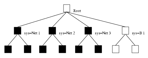
FIGURE 3-3 Local and Remote Objects as Seen from MIS Net 1When SA2 connects to MIS Net 1, the Management Information Tree (MIT) displays objects from Net 1, Net 2, and Net 3. Refer to the following figure for an illustration. Solid black squares represent remote objects. In this case, Net 1, Net 2, and Net 3 are connected to each other. For example, Net 1 connects to Net 2 and Net 3.
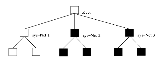
FIGURE 3-4 Local and Remote Objects as Seen From MIS Net 2When SA3 connects to MIS Net 3, the MIT only contains objects that are local to Net 3, as illustrated in the following figure.
In this scenario, it would be possible to let SA3 see objects from Net 2 and Net 1 by mounting Net 1 and Net 2 on Net 3. Refer to the following figure. This mount would give SA3 the same access and view as SA2
.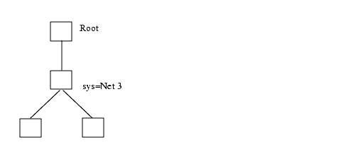
FIGURE 3-5 Objects Seen From MIS Net 33.3 Establishing MIS Connections
Use MIS Connections to establish a connection between your local MIS and a remote MIS. You can set up your system so that multiple MISs are connected continuously. Also, you can use MIS Connections application to connect on a one-time basis to a remote MIS.
MIS Connections is normally started from the Network Tools as described in the following procedure.

To Establish an MIS Connection
From the Network Tools Window
- Click Administration Tool \xd4 MIS Connections.
From the Command Line
- Type:
- em_mismgr [options]
- Refer to the following table for a list of optional parameters.
3.4 Sharing Data Between Connected MISs
Once you are connected to another MIS you have these options:
- Use the default Event Forwarding Discriminators (EFD) to make data about all events available to the other MIS.
- Define a non-default EFD to make only data about selected events available to the other MIS. (This option applies when you want to filter out event types.)
EFDs are mechanisms for disseminating event information. They are a managed object class defined in ISO DMI (ITU X.721 ISO/IEC 10165-2). EFDs include a discriminator construct attribute (frequently referred to as a discriminator), a destination attribute, and optional attributes. The discriminator construct specifies a filter that MIS uses to test event information. Event information that passes the test is sent to each destination specified by an EFD destination attribute.
When an EFD passes event information from one MIS to another, the MIS that sends the event acts as the agent; the MIS that receives the event acts as the manager.
3.4.1 Accessing Data About All Events
To make data about all event types available to other MISs in your network, perform the following procedure.

To Access Data About All Events
1. In the Network Tools window, select Administration \xd4 MIS Connections.
- The MIS Connections window is displayed, as shown in the following figure.

FIGURE 3-6 MIS Connections Window2. In the MIS Host field, type the name of the remote MIS.3. Click Connect.
- MIS Connections uses the default EFD to establish a connection with the specified MIS. Your local and remote MISs now share information.
- The default EFD consists of the definition and:{}.
Caution – This definition causes all events to be forwarded.
3.4.2 Accessing Data about Selected Events
To make data about selected event types available to other MISs, perform the following procedure.

To Access Data About Selected Events
1. In the Network Tools window, select Administration \xd4 MIS Connections.2. Click Advanced..
- MIS Manager displays the Advanced window, as shown in the following figure.
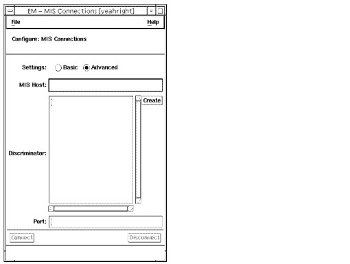
FIGURE 3-7 MIS Connections Advanced Settings Window3. In the MIS Host field, type the name of the machine on which the remote MIS is running.4. In the Discriminator field, define the Event Forwarding Discriminator (EFD).
- For information on Common Management Information Service (CMIS) filtering, refer to the Customizing Guide and Managing Your Network.
5. In the Port field, type the remote port number for the connection.
- The default port number is 5555. You can type a non-default port number in this field.
6. Click Connect.
- MIS Connections uses the non-default EFD to establish a connection with the specified MIS. Now your local and remote MIS share information.
3.5 Re-establishing a Remote MIS Link
Whenever a remote MIS link is re-established or goes down, an alarm is sent to MIS. The alarm will indicate if the remote MIS is down, or the remote MIS is up with an alarm/notification called connectivityChange. This will also cause an update of the network topology in Viewer, if the Viewer is running. The Connection Manager broadcasts a communicationsAlarm to the appropriate applications. The event(s) are logged into the Log Manager where they will display.
|
Sun Microsystems, Inc. Copyright information. All rights reserved. |
Doc Set | Contents | Previous | Next | Index |