Chapter 1 Product Overview
Standard Features
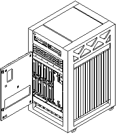
The Sun Enterprise 3500 system enclosure contains a 5-slot chassis and two built-in disk banks that hold up to eight FC-AL (Fibre Channel-Arbitrated Loop) disk drives.
Figure 1-1 Sun Enterprise 3500 System

The minimum configuration for the server is:
-
Power/cooling modules (PCMs) or PCM filler panels
-
Fan tray
-
Clock+ board
-
CPU/Memory+ board
-
UltraSPARC(TM)II module
-
Main memory
-
I/O+ board
-
Board filler panels for any unpopulated board slots
-
Interface board (IB) or IB filler panel
-
Peripheral power supply w/AC power sequencer
-
Auxiliary peripheral power supply or thermal protection module
-
Media tray for removable media, including CD-ROM drive
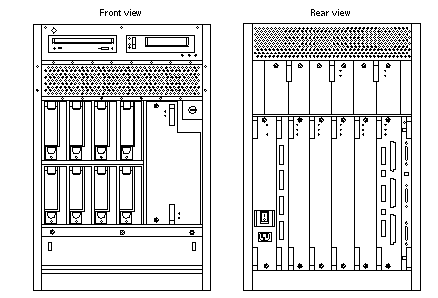
Figure 1-2 Sun Enterprise 3500 Components

Note -
System components are identified in the Appendix F, Illustrated Parts Breakdown. See Figure F-1 and Figure F-2, and the Table F-2.
Internal Options
Table 1-1 Internal Options for the Sun Enterprise 3500 System|
Option |
Quantity |
Comments |
|
|---|---|---|---|
|
CPU/Memory+ boards, SBus+ I/O boards, Graphics+ I/O boards, PCI+ I/O boards |
5 total per system |
Each slot can accept four types of boards: CPU/Memory+ board, SBus+ I/O board, Graphics+ I/O board, and PCI+ I/O board. Combinations can vary. Since slot 1 connects to the onboard SCSI devices, however, this slot should be reserved for the first I/O+ board. One system board becomes the system master automatically. Jumper changes are not needed. |
|
|
UltraSPARC II modules |
8 per system |
|
0-2 modules on each CPU/Memory+ board. |
|
Memory modules |
0, 8, or 16 SIMMs per CPU/Memory+ board |
SIMM sizes are 8, 32, or 128 Mbyte DRAM. Do not mix sizes within the same bank. Add 8 SIMMs at a time. Install SIMMs in all bank 0 sockets first on each CPU/Memory+ board, from the lowest slot to the highest. Once bank 0 is full, install remaining SIMMs in bank 1 sockets in the same order. |
|
|
SBus cards |
12 per system |
|
0-3 cards per SBus+ I/O board, 0-2 cards per Graphics+ I/O board. |
|
Graphics (UPA) cards |
4 per system |
|
1 card per Graphics+ I/O board. |
|
PCI cards |
Dependent upon card type, consult your customer representative |
0-2 cards per PCI+ I/O board. |
|
|
Media tray |
CD-ROM drive and optional tape drive |
Media tray takes removable-media drives only. One SunCD 32 is standard equipment per system. One optional tape drive is supported in the media tray. |
|
|
Interface board |
1 per system |
|
4 GBIC slots on the interface board (2 GBICs per I/O+ board). |
|
Disk drives |
8 internal disk bays |
Top bank can hold 4 disk drives; bottom bank can hold 4 disk drives. Install disks in bottom bank first, from left to right, starting with bay 0 (the farthest bay to the left as you face the front of the system is bay 0. Note: Reserve bay 0 for boot disk). Also install disks in top bank from left to right. |
|
- © 2010, Oracle Corporation and/or its affiliates
