Chapter 9 Troubleshooting Overview
Using a Terminal
If your system does not normally have a terminal, you may find it useful to attach a console terminal directly to the system for troubleshooting.
Note -
Alternatively, you can log in remotely through a network. You can also control the system remotely through a modem and a system serial port.
To attach a terminal to the system:
-
Halt the system and turn off power.
-
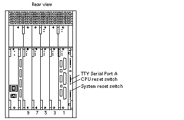
Connect the terminal to serial port A on the clock+ board.
The clock+ board is located at the back of system. See Figure 9-1.
-
Power on the terminal.
-
Set up the terminal.
Refer to the OpenBoot Command Reference for instructions for using the set-defaults and printenv commands.
The settings will vary with the terminal type, but these settings are often used:
-
9600 bps
-
8 data bits
-
1 stop bit
-
Even parity
-
Full duplex
-
-
Power on the system and reboot.
Figure 9-1 Details of the Clock+ Board

Reset Switches
In the event that the system hangs, reset the system by pressing the system reset switch (marked ![]() ) on the clock+ board. See Figure 9-1.
) on the clock+ board. See Figure 9-1.
A second button, the CPU reset switch (marked (CPU) ![]() ), is useful during software debugging.
), is useful during software debugging.
Hardware Indicators
Many LEDs are used to indicate the status of the system. Figure 9-2 shows the meanings of the symbols marked on the front panel and also on individual boards and modules.
Figure 9-2 LED Symbols

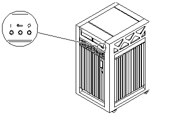
Figure 9-3 shows the location of the front panel LEDs. In normal operation, two green LEDs are lit, Power and Cycling.
Figure 9-3 Front Panel LEDs

Table 9-1 lists complete LED codes for the system front panel.
Table 9-1 System Front Panel LED Codes|
Power |
Service |
Running |
Condition |
|---|---|---|---|
|
Off |
Off |
Off |
System has no power. |
|
Off |
On |
Off |
Failure mode. |
|
Off |
Off |
On |
Failure mode. |
|
Off |
On |
On |
Failure mode. |
|
On |
Off |
Off |
System is hung, either in POST/OpenBoot or in the operating system. |
|
On |
Off |
On |
Hung in OS. |
|
On |
On |
Off |
(1) Hung in POST/OBP or (2) hung in OS and failed component on board. |
|
On |
On |
On |
(1) Hung in POST/OBP or (2) hung in OS and failed component on board. |
|
On |
Off |
Flash |
OS running. |
|
On |
On |
Flash |
OS running and failed component on board. |
|
On |
Flash |
Off |
Slow flash = POST. Fast flash = OBP. |
|
On |
Flash |
On |
Undefined. |
Clock+ Board LEDs
The LED codes for the clock+ board are the same as for the front panel, except the clock+ board uses this symbol ![]() instead of a vertical bar to indicate that the board is receiving electrical power.
instead of a vertical bar to indicate that the board is receiving electrical power.
CPU/Memory+ and I/O+ Board LEDs
Most of the codes for the CPU/Memory+ and I/O+ board LEDs are similar to codes for the front panel and clock+ board. The major exception is the second code (Off-On-Off). For hot-pluggable boards, this code indicates that the board is in low power mode and is ready to remove.
If the Running LED is lit or flashing, do not remove the board. Electrical shorting will result, damaging the board and the system.
Table 9-2 lists all LED codes for the CPU/Memory+ and I/O+ boards.
Table 9-2 LED Codes for the CPU/Memory+ and I/O+ Boards|
Power |
Service |
Running |
Condition |
|---|---|---|---|
|
Off |
Off |
Off |
Board has no electrical power. |
|
Off |
On |
Off |
Board is in low power mode, can be unplugged. |
|
Off |
Off |
On |
Undefined. |
|
Off |
On |
On |
Undefined. |
|
On |
Off |
Off |
System is hung, either in POST/OpenBoot or in the operating system. |
|
On |
Off |
On |
Hung in OS. |
|
On |
On |
Off |
(1) Hung in POST/OBP or (2) hung in OS and failed component on board. |
|
On |
On |
On |
(1) Hung in POST/OBP or (2) hung in OS and failed component on board. |
|
On |
Off |
Flash |
OS running. |
|
On |
On |
Flash |
OS running and failed component on board. |
|
On |
Flash |
Off |
Slow flash = POST. Fast flash = OBP. |
|
On |
Flash |
On |
Undefined. |
The general rules for the CPU/Memory+ and I/O+ boards are:
-
If no LEDs are lit, there is no electrical power to the board.
-
If the green LEDs (Power and Running) are not lit, the board is ready for removal.
-
If no LEDs are flashing, the system is hung.
-
The board requires service if the yellow Service LED is lit continuously (not flashing). Note that it is a normal condition for the Service LED to flash during POST testing.
Power Supplies
There are several types of power supply modules, but all have two LEDs. The locations of the green (power) LED and the yellow (service) LED vary according to the module type.
Peripheral Power Supplies
The system has one peripheral power supply/AC unit (PPS/AC), located at the rear of the cabinet.
The system may also have the optional auxiliary peripheral power supply (PPS), located at the front of the cabinet. If the auxiliary PPS is not installed, the slot contains a thermal protection module.
On both the PPS/AC and the PPS, the green Component Power LED is located above the yellow Service LED. The Component Power LED is lit when the power supply is operating, but does not necessarily indicate that the DC outputs are fully within specification. The yellow Service LED is lit when a DC power output has failed or a voltage level is out of specification.
Power/Cooling Modules
The system has up to three power/cooling modules (PCMs).
Each PCM has two LEDs. The green Component Power LED is located below the yellow Service LED. Table 9-3 summarizes the LED codes for the PCM.
Table 9-3 PCM LED Codes|
Component Power |
Service |
Condition |
|---|---|---|
|
Off |
Off |
No AC input. |
|
On |
Off |
Normal operation. |
|
On |
On |
A fan has failed. |
|
Off |
On |
One or more DC outputs have failed or the voltages are out of specification. |
Disk Tray Indicators
The availability and type of status information varies with the disk tray type used in a system. Refer to the disk tray user manual for specific status information.
Card Cage Slot Information
When installing a board, remember:
-
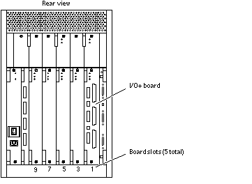
Slot numbers--board slots are numbered 1, 3, 5, 7, 9, from right to left (see Figure 9-4). See "Card Cage" for an explanation of the missing even-numbered slots.
-
Slot functions--slot 1 should contain an I/O+ board (connects to media tray).
Aside from the requirement for the I/O+ board, all five card cage slots are equivalent.
Figure 9-4 Slot Numbers for the Card Cage

For a more complete set of rules for configuring the system, see Appendix D, Rules for System Configuration.
Diagnosing Problems
Servicing Obvious Problems
If the Service LED on the system front panel (or the clock+ board) indicates a hardware failure, find the failing module by looking for a lit service LED on the individual module.
The system contains a number of hot-pluggable modules. Under limited conditions, these modules can be removed and replaced while the system continues running. (For a general description of the hot-plug feature, see "Hot-Plug Feature".)
The hot-pluggable modules include these types: CPU/Memory+ board, SBus+ I/O board, Graphics+ I/O board, PCI+ I/O board, and PCM.
The hot-plug feature requires a functional peripheral power supply/AC. If the peripheral power supply cannot provide current, the hot-pluggable module will be damaged if you attempt to remove or replace it.
If a module fails and there are redundant resources in the system, it may be safe to leave the module in a running system until a replacement part is delivered. For example, if a CPU fails (as indicated perhaps by system messages), but other CPUs continue to function in the system, you can leave the CPU/Memory+ board in place until a replacement CPU is available. Note that it is particularly helpful to leave a module in place if you do not have a filler panel to replace it.
If you choose to remove a faulty board or PCM, remember that you must fill the vacated slot with a replacement or a filler panel to prevent the system from overheating.
Troubleshooting Less Obvious Problems
When board LED codes do not specify the failing hardware, several types of software programs are available to supply information about the problem. This software includes the SunVTS(TM) program, the prtdiag command, the prtenv command, POST and OpenBoot PROM commands, and the SyMON(TM) program.
SunVTS
Run SunVTS(TM) under the Solaris operating environment, or equivalent.
The SunVTS online validation test suite is designed to stress test Sun hardware. By running multiple and multithreaded diagnostic hardware tests, the SunVTS software verifies the system configuration and functionality of most hardware controllers and devices.
SunVTS tests many board and system functions, as well as interfaces for Fibre Channel, SCSI, and SBus interfaces. SunVTS accepts user-written scripts for automated testing.
Refer to the SunVTS User's Guide for starting and operating instructions.
prtdiag Command
You can use the prtdiag command to display:
-
Diagnostic information
-
Failed field replaceable units (FRUs)
Refer to the prtdiag man page for instructions.
History Log Option
To isolate an intermittent failure, it can be helpful to maintain a prtdiag history log. Use the prtdiag command with the -l (log) option to send output to a log file in the /var/adm directory.
Running prtdiag
% /usr/platform/sun4u/sbin/prtdiag
% /usr/platform/sun4u/sbin/prtdiag -l
POST and OpenBoot
POST and OpenBoot work together in the system to test and manage system hardware.
POST resides in the OpenBoot PROM on each CPU/Memory+ board and I/O+ board. When the system is turned on, or if a system reset is issued, POST detects and tests buses, power supplies, boards, CPUs, SIMMs, and many board functions. POST controls the status LEDs on the system front panel and all boards. POST displays diagnostic and error messages on a console terminal, if available.
Only POST can configure the system hardware, and only POST can enable hot-pluggable boards. If a new PCM is added to the card cage after the system has booted, the new PCM will not work until the system is rebooted, at which time POST reconfigures the system, using the PCMs that are found in the system at that time.
OpenBoot provides basic environmental monitoring, including detection of overheating conditions and out-of-tolerance voltages. For example, if an overheated board is found, OpenBoot issues a warning message. If the temperature passes the danger level, POST will put the overheated board(s) in low power mode.
OpenBoot also provides a set of commands and diagnostics at the ok prompt. For example, you can use OpenBoot to set NVRAM variables that reserve a board or a set of SIMMs for hot-sparing.
The following OpenBoot commands may be useful for diagnosing problems:
show-devs Command
Use the show-devs command to list the devices that are included in the system configuration.
printenv Command
Use the printenv command to display the system configuration variables stored in the system NVRAM. The display includes the current values for these variables, as well as the default values.
If the system cannot communicate with a 10BASE-T network, the Ethernet link test setting for the port may be incompatible with the setting at the network hub. See "Failure of Network Communications" for further details.
probe-scsi Command
The probe-scsi command locates and tests SCSI devices attached to the system. probe-scsi is run from the OpenBoot prompt.
When it is not practical to halt the system, you can use SunVTS as an alternate method of testing the SCSI interfaces.
Reference Documents for POST/OpenBoot
-
OpenBoot 3.x Command Reference, part number 802-3242
-
Writing FCode 3.x Programs, part number 802-3230
Solstice SyMON
The Solstice(TM) SyMON program monitors system functioning and features a graphical user interface (GUI) to continuously display system status. Solstice SyMON is intended to complement system management tools such as SunVTS.
Solstice SyMON is accessible through an SNMP interface from network tools such as Solstice SunNet Manager(TM).
Refer to the Solstice SyMON User's Guide manual, part number 802-5355, for starting and operating instructions.
Specific Problems and Solutions
Failure of Network Communications
Description of the Problem
The system cannot communicate with a network if the system and the network hub are not set in the same way for the Ethernet link integrity test. This problem particularly applies to 10BASE-T network hubs, where the Ethernet link integrity test is optional. This is not a problem for 100BASE-T networks, where the test is enabled by default.
If you connect the system to a network and the network does not respond, use the OpenBoot command watch-net-all to display conditions for all network connections:
ok watch-net-all
For SBus Ethernet cards, the test can be enabled or disabled with a hardware jumper, which you must set manually. For the TPE and MII onboard ports on the I/O+ board, the link test is enabled or disabled through software, as shown below.
Remember also that the TPE and MII ports are not independent circuits and as a result, both ports cannot be used at the same time.
Note -
Some hub designs do not use a software command to enable/disable the test, but instead permanently enable (or disable) the test through a hardware jumper. Refer to the hub installation or user manual for details of how the test is implemented.
Determining the Device Names of the I/O+ Boards
To enable or disable the link test for an onboard TPE (hme) port, you must first know the device name for the I/O+ board. To list the device names:
-
Shut down the system and take the system into OpenBoot.
-
Determine the device names of the I/O+ boards:
Solution 1-- while the operating system is running:
-
Become superuser.
-
# eeprom nvramrc="probe-all install-console banner apply disable-link-pulse
device-name "
  (Repeat for any additional device names.)
# eeprom "use-nvramrc?"=true
-
Reboot the system (when convenient) to make the changes effective.
Solution 2 -- when the system is already in OpenBoot:
-
At the monitor OpenBoot prompt, type:
ok nvedit
0: probe-all install-console banner
1: apply disable-link-pulse device-name
(Repeat this step for other device names as needed.)
(Press CONTROL-C to exit nvedit.)
ok nvstore
ok setenv use-nvramrc? true
-
Reboot to make the changes effective.
Using a Remote Console
It is possible to reset the system or cycle power from the remote console under these conditions:
-
The console must be connected to port A on the clock+ board.
-
The key switch must be in either the On or Diagnostic setting. If the key switch is in the Secure or Off position, the remote key sequences and button resets are ignored.
-
Security features permit the use of the remote console.
-
You must use a slow typing speed, not less than 0.5 seconds and not more than 5 seconds between characters.
|
Command |
Enter this sequence |
|---|---|
|
Remote power off/on |
Return Return ~ Control-Shift-p |
|
Remote system reset |
Return Return ~ Control-Shift-r |
|
Remote XIR (CPU) reset |
Return Return ~ Control-Shift-x |
|
Key: Return = ASCII 0d hexadecimal, ~ (tilde) = ASCII 7e hexadecimal, Control-Shift-p = 10 hexadecimal, Control-Shift-r = 12 hexadecimal, Control-Shift-x = 18 hexadecimal. |
|
Note -
The remote console logic circuit continues to receive power, even if you have commanded system power off.
The remote system reset command is useful for resetting the system under general conditions. The remote XIR reset command is used for software development and debugging.
- © 2010, Oracle Corporation and/or its affiliates
