Hardware Indicators
Many LEDs are used to indicate the status of the system. Figure 9-2 shows the meanings of the symbols marked on the front panel and also on individual boards and modules.
Figure 9-2 LED Symbols

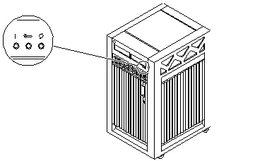
Figure 9-3 shows the location of the front panel LEDs. In normal operation, two green LEDs are lit, Power and Cycling.
Figure 9-3 Front Panel LEDs

Table 9-1 lists complete LED codes for the system front panel.
Table 9-1 System Front Panel LED Codes|
Power |
Service |
Running |
Condition |
|---|---|---|---|
|
Off |
Off |
Off |
System has no power. |
|
Off |
On |
Off |
Failure mode. |
|
Off |
Off |
On |
Failure mode. |
|
Off |
On |
On |
Failure mode. |
|
On |
Off |
Off |
System is hung, either in POST/OpenBoot or in the operating system. |
|
On |
Off |
On |
Hung in OS. |
|
On |
On |
Off |
(1) Hung in POST/OBP or (2) hung in OS and failed component on board. |
|
On |
On |
On |
(1) Hung in POST/OBP or (2) hung in OS and failed component on board. |
|
On |
Off |
Flash |
OS running. |
|
On |
On |
Flash |
OS running and failed component on board. |
|
On |
Flash |
Off |
Slow flash = POST. Fast flash = OBP. |
|
On |
Flash |
On |
Undefined. |
Clock+ Board LEDs
The LED codes for the clock+ board are the same as for the front panel, except the clock+ board uses this symbol ![]() instead of a vertical bar to indicate that the board is receiving electrical power.
instead of a vertical bar to indicate that the board is receiving electrical power.
CPU/Memory+ and I/O+ Board LEDs
Most of the codes for the CPU/Memory+ and I/O+ board LEDs are similar to codes for the front panel and clock+ board. The major exception is the second code (Off-On-Off). For hot-pluggable boards, this code indicates that the board is in low power mode and is ready to remove.
If the Running LED is lit or flashing, do not remove the board. Electrical shorting will result, damaging the board and the system.
Table 9-2 lists all LED codes for the CPU/Memory+ and I/O+ boards.
Table 9-2 LED Codes for the CPU/Memory+ and I/O+ Boards|
Power |
Service |
Running |
Condition |
|---|---|---|---|
|
Off |
Off |
Off |
Board has no electrical power. |
|
Off |
On |
Off |
Board is in low power mode, can be unplugged. |
|
Off |
Off |
On |
Undefined. |
|
Off |
On |
On |
Undefined. |
|
On |
Off |
Off |
System is hung, either in POST/OpenBoot or in the operating system. |
|
On |
Off |
On |
Hung in OS. |
|
On |
On |
Off |
(1) Hung in POST/OBP or (2) hung in OS and failed component on board. |
|
On |
On |
On |
(1) Hung in POST/OBP or (2) hung in OS and failed component on board. |
|
On |
Off |
Flash |
OS running. |
|
On |
On |
Flash |
OS running and failed component on board. |
|
On |
Flash |
Off |
Slow flash = POST. Fast flash = OBP. |
|
On |
Flash |
On |
Undefined. |
The general rules for the CPU/Memory+ and I/O+ boards are:
-
If no LEDs are lit, there is no electrical power to the board.
-
If the green LEDs (Power and Running) are not lit, the board is ready for removal.
-
If no LEDs are flashing, the system is hung.
-
The board requires service if the yellow Service LED is lit continuously (not flashing). Note that it is a normal condition for the Service LED to flash during POST testing.
Power Supplies
There are several types of power supply modules, but all have two LEDs. The locations of the green (power) LED and the yellow (service) LED vary according to the module type.
Peripheral Power Supplies
The system has one peripheral power supply/AC unit (PPS/AC), located at the rear of the cabinet.
The system may also have the optional auxiliary peripheral power supply (PPS), located at the front of the cabinet. If the auxiliary PPS is not installed, the slot contains a thermal protection module.
On both the PPS/AC and the PPS, the green Component Power LED is located above the yellow Service LED. The Component Power LED is lit when the power supply is operating, but does not necessarily indicate that the DC outputs are fully within specification. The yellow Service LED is lit when a DC power output has failed or a voltage level is out of specification.
Power/Cooling Modules
The system has up to three power/cooling modules (PCMs).
Each PCM has two LEDs. The green Component Power LED is located below the yellow Service LED. Table 9-3 summarizes the LED codes for the PCM.
Table 9-3 PCM LED Codes|
Component Power |
Service |
Condition |
|---|---|---|
|
Off |
Off |
No AC input. |
|
On |
Off |
Normal operation. |
|
On |
On |
A fan has failed. |
|
Off |
On |
One or more DC outputs have failed or the voltages are out of specification. |
Disk Tray Indicators
The availability and type of status information varies with the disk tray type used in a system. Refer to the disk tray user manual for specific status information.
- © 2010, Oracle Corporation and/or its affiliates
