System Overview
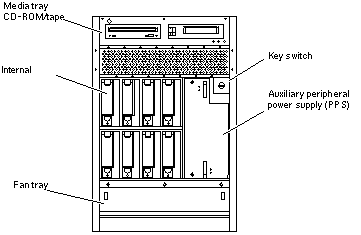
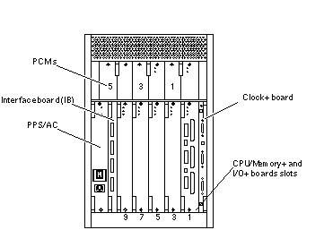
This section describes the Enterprise 3500 system enclosure. See Figure B-1 and Figure B-2.
The front of the cabinet contains the CD-ROM/tape drives, the key switch, the internal disk drives, the auxiliary peripheral power supply (PPS1) or thermal protection module, and the fan tray.
The rear of the cabinet contains the peripheral power supply/AC (PPS0, with power switch and AC cable socket), the clock+ board, the interface board (optional) or filler panel, the board slots, and the PCM slots.
Air circulation inside the cabinet is provided by fans in the power/cooling modules and in the fan tray. The PCMs have two fans each. The fans provide cooling for the PCM itself, plus two adjacent board slots. PCM slot 5 must contain either a fan tray or a spare PCM. These fans cool the peripheral power supply.
Note -
PCM slot 5 may contain either an auxiliary fan tray or a spare PCM.
All empty slots require filler panels for proper airflow, cooling, and EMI protection.
Figure B-1 Enterprise 3500 System - Front View

Figure B-2 Enterprise 3500 System - Rear View

Board Types
-
The CPU/Memory+ board supports up to two UltraSPARC II CPU modules and 16 SIMM slots.
-
The SBus+ I/O board includes two SYSIO ASICs that provide two SBuses: one for two plug-in SBus cards and two GBIC (100 MB/sec Fibre Channel) interfaces, and one for one plug-in SBus card and the onboard devices (10/100 Mbit TPE and Single-ended Fast/Wide SCSI).
-
The Graphics+ I/O board includes one SYSIO ASIC that provides a single SBus for two plug-in SBus cards, two GBIC (100 MB/sec Fibre Channel) interfaces, and the onboard devices (10/100 Mbit TPE and Single-ended Fast/Wide SCSI).
-
The PCI+ I/O board has two PCI bus connectors, each of which can accommodate a PCI riser card. Each riser card accommodates one PCI short card. In addition, onboard devices provide Fast Ethernet (10/100 Mbit) and Fast Wide SCSI interfacing.
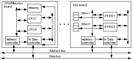
The Enterprise 3500 server features a high-speed centerplane bus that includes separate address and data buses.
There are few differences between board slots and each slot can accept any board type. However, an I/O+ board should be installed in slot 1 since this slot connects directly to the internal media tray through the centerplane and related cables. The internal tape and/or CD-ROM drives cannot be used unless an I/O+ board is present in slot 1.
Figure B-3 Enterprise System Logical Organization

- © 2010, Oracle Corporation and/or its affiliates
