Appendix B Functional Description
The 5-slot Enterprise 3500 system is part of the Sun Enterprise server family, which includes the 16-slot and 8-slot cabinet servers and an 8-slot standalone server.
All systems feature shared-memory multiprocessors and use the same boards, power/cooling modules (PCMs), and operating software.
System Overview
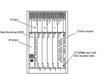
This section describes the Enterprise 3500 system enclosure. See Figure B-1 and Figure B-2.
The front of the cabinet contains the CD-ROM/tape drives, the key switch, the internal disk drives, the auxiliary peripheral power supply (PPS1) or thermal protection module, and the fan tray.
The rear of the cabinet contains the peripheral power supply/AC (PPS0, with power switch and AC cable socket), the clock+ board, the interface board (optional) or filler panel, the board slots, and the PCM slots.
Air circulation inside the cabinet is provided by fans in the power/cooling modules and in the fan tray. The PCMs have two fans each. The fans provide cooling for the PCM itself, plus two adjacent board slots. PCM slot 5 must contain either a fan tray or a spare PCM. These fans cool the peripheral power supply.
Note -
PCM slot 5 may contain either an auxiliary fan tray or a spare PCM.
All empty slots require filler panels for proper airflow, cooling, and EMI protection.
Figure B-1 Enterprise 3500 System - Front View
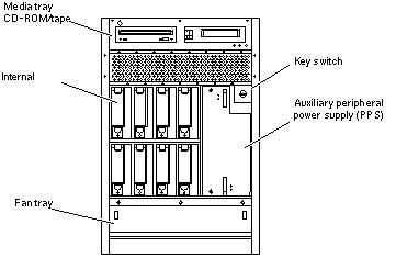
Figure B-2 Enterprise 3500 System - Rear View
Board Types
-
The CPU/Memory+ board supports up to two UltraSPARC II CPU modules and 16 SIMM slots.
-
The SBus+ I/O board includes two SYSIO ASICs that provide two SBuses: one for two plug-in SBus cards and two GBIC (100 MB/sec Fibre Channel) interfaces, and one for one plug-in SBus card and the onboard devices (10/100 Mbit TPE and Single-ended Fast/Wide SCSI).
-
The Graphics+ I/O board includes one SYSIO ASIC that provides a single SBus for two plug-in SBus cards, two GBIC (100 MB/sec Fibre Channel) interfaces, and the onboard devices (10/100 Mbit TPE and Single-ended Fast/Wide SCSI).
-
The PCI+ I/O board has two PCI bus connectors, each of which can accommodate a PCI riser card. Each riser card accommodates one PCI short card. In addition, onboard devices provide Fast Ethernet (10/100 Mbit) and Fast Wide SCSI interfacing.
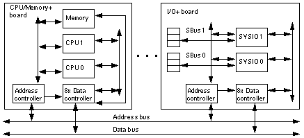
The Enterprise 3500 server features a high-speed centerplane bus that includes separate address and data buses.
There are few differences between board slots and each slot can accept any board type. However, an I/O+ board should be installed in slot 1 since this slot connects directly to the internal media tray through the centerplane and related cables. The internal tape and/or CD-ROM drives cannot be used unless an I/O+ board is present in slot 1.
Figure B-3 Enterprise System Logical Organization
Board Hot-Swapping Procedures
The CPU/Memory+ board and the I/O+ boards are hot-swappable under certain conditions. If the operating system detects a hardware failure in the board, the system powers down the corresponding board slot and turns off the left green status LED on the board. (There are three status LEDs on each board. See Table 9-2 for the board LED codes.)
When the left green LED is off, it is safe to remove the board.
CPU/Memory+ Board
The system will support up to three CPU/Memory+ boards. All empty card cage slots must have a filler panel installed.
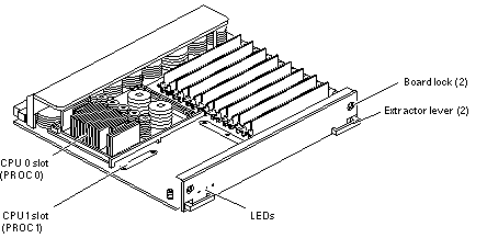
The CPU/Memory+ board (see Figure B-4) supports up to 2 CPU modules and 16 SIMMs.
Figure B-4 CPU/Memory+ Board
CPU Modules
Each CPU/Memory+ board has two sets of CPU connectors, marked PROC 0 and PROC 1.
The order in which you fill CPU slots is not critical. However, to optimize heat dissipation in the system:
-
Fill all PROC 0 locations on all CPU/Memory+ boards before filling any PROC 1 locations. To receive the maximum quantity of diagnostic information, fill PROC 0 on board 3.
-
After all PROC 0 locations are filled, you may begin filling the PROC 1 locations, again starting from the lowest slot number to the highest.
The Table B-1 table shows where five CPU modules are installed on three CPU/Memory+ boards (example only). Two board slots (1 and 9) do not have CPU/Memory+ boards installed because slot 1 is reserved for an I/O+ board, and in this example, slot 9 has a filler panel installed.
Table B-1 Five CPUs on Three Boards|
Board Slot Number |
CPU Slot PROC 0 |
CPU Slot PROC 1 |
|---|---|---|
|
1 - Reserved, I/O+ board |
||
|
3 |
in |
in |
|
5 |
in |
in |
|
7 |
in |
|
|
9 - Filler panel installed |
||
System Master
The board slots are interchangeable. A system master board is selected for the duration of POST and OBP testing to control the testing processes. The system master is normally the lowest-numbered slot containing a board with a functional CPU. After the tests are finished, the board slots are again fully equivalent.
SIMMs
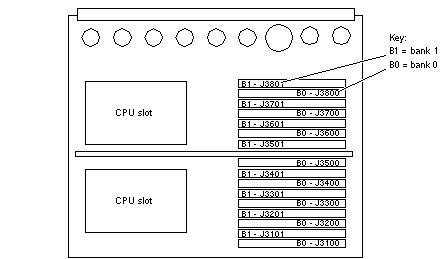
The CPU/Memory+ board has 16 slots for SIMMs, organized as two banks of eight SIMMs.
Slot Locations
SIMMs must be installed in full banks of eight. Figure B-5 shows the slot numbers for bank 0 and bank 1.
Figure B-5 SIMM Slot Locations
SIMM Selection
The JEDEC standard 3.3 volt SIMMs are available in 8, 32, or 128 Mbyte capacities. All are 168-pin SIMMs.
Do not mix different capacities in a bank.
I/O+ Boards
Several types of I/O+ boards are available: SBus+ I/O board, Graphics+ I/O board, and PCI+ I/O board.
Note -
Board slot 1 requires an I/O+ board because this is the only slot that connects with the internal media tray. If slot 1 does not contain an I/O+ board, the drives in the media tray will not function.
Note -
All empty card cage slots must contain a filler panel.
SBus+ I/O Board
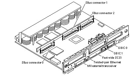
The SBus+ I/O board with 100 MB/sec Fibre Channel (see Figure B-6) includes two SYSIO ASICs that provide two SBuses:
-
One for two plug-in SBus cards and two GBIC (100 MB/sec Fibre Channel) interfaces
-
One for one plug-in SBus card and the onboard devices (10/100 Mbit TPE and Single-ended Fast/Wide SCSI)
Note -
SBus connector slots 1 and 2 on the SBus+ I/O board can accommodate a double-wide SBus card.
Figure B-6 SBus+ I/O Board
Graphics+ I/O Board
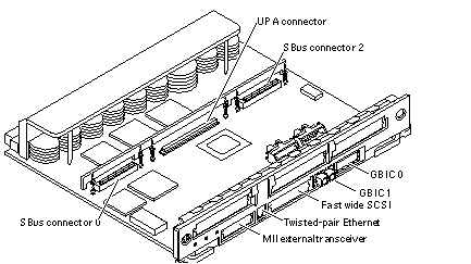
The Graphics+ I/O board with 100 MB/sec Fibre Channel (see Figure B-7) includes one SYSIO ASIC that provides a single SBus for two plug-in SBus cards, two GBIC (100 MB/sec Fibre Channel) interfaces, and the onboard devices (10/100 Mbit TPE and Single-ended Fast/Wide SCSI).
Figure B-7 Graphics+ I/O Board
PCI+ I/O Board
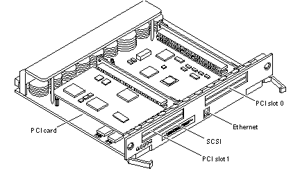
The PCI+ I/O board (see Figure B-8) has two PCI bus connectors:
-
Each connector can accommodate a PCI riser card
-
Each riser card accommodates one PCI short card
In addition, onboard devices on the PCI+ I/O board provide Fast Ethernet (10/100 Mbit) and Fast Wide SCSI interfacing.
Figure B-8 PCI+ I/O Board
The board contains five subsystems: IO(PCI Bus), Memory, Bus Interface, FireHose Interface, and Clock Generation. Four of these subsystems: the IO(PCI Bus), Memory, Bus Interface and internal board interface subsystems include ASICs. The Clock subsystem distributes and generate clocks for the ASICs and PCI Bus Interfaces on the board.
Power Supplies
There are three types of power supplies: power/cooling modules (PCMs), auxiliary peripheral power supply (optional), and peripheral power supply/AC. PCMs provide DC current and cooling air to boards in the card cage. The peripheral power supply provides current for peripheral devices (such as a tape or CD-ROM drive) in the media tray. The peripheral power supply/AC provides current for peripheral devices, and has the AC switch and AC cable socket.
Power/Cooling Modules
Figure B-9 PCM
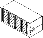
The DC power to the centerplane is supplied by one or more PCMs. Each PCM also provides cooling air for two board slots. If a slot contains a board, the adjacent PCM slot must contain a PCM to supply cooling air.
The system has a maximum capacity of three PCMs. The slot above the peripheral power supply/AC may have either a PCM or a fan tray.
Current from individual PCMs is shared on the centerplane.
With automatic system reconfiguration (ASR), a PCM can be taken offline and replaced without halting the system. There are two restrictions:
-
The remaining power/cooling modules must provide sufficient electrical power. As a general rule, the number of boards must be less than half the number of PCMs.
-
The PCM should be replaced quickly so that any adjacent boards will not overheat from lack of fan cooling.
Peripheral Power Supply/AC
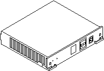
The system has one peripheral power supply/AC input (PPS/AC) installed in the rear of the system. The PPS/AC, also known as PPS 0 to the system software, has the AC switch and AC cable socket.
Additionally, the peripheral power supply/AC provides DC power for the CD-ROM/tape drives tray and precharge power for hot-plugging boards and PCMs.
Figure B-10 Peripheral Power Supply/AC
Peripheral Power Supply
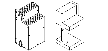
In the front of the system is a slot for an optional auxiliary peripheral power supply (PPS). The PPS, also known as PPS1 to the system software, supplies redundant current for the peripheral devices.
If an auxiliary peripheral power supply is not installed, a thermal protection module must be installed in the PPS slot.
A thermal protection module or a power supply is required in the PPS1 slot to ensure maximum operating temperature is not exceeded.
Figure B-11 Auxiliary Peripheral Power Supply and Thermal Protection Module
Clock+ Board
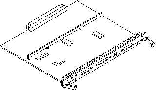
The clock+ board is located at the rear of the cabinet, at the right side of the card cage. See Figure B-12.
The clock+ board receives cooling air from the PCM located above the two board slots on the right side of the card cage.
The clock+ board provides 16 pairs of system clocks, 32 pairs of processor clocks.
The processor clock frequency is set to match the lowest-frequency processor in the system. All processors run at the same clock speed. The system clock and the processor clocks are derived from a single clock source. The frequency of the clock source as well as the processor and system clocks are programmable and set by firmware.
The clock+ board also includes central devices including serial ports, keyboard and mouse, and a time of day (TOD) chip.
Figure B-12 Clock+ Board
Network Interfaces
Each I/O+ board has an onboard Ethernet circuit, connected to an RJ-45 twisted-pair connector and a 40-pin media independent interface (MII) connector. The circuit automatically adapts to 10 Mbit or 100 Mbit at the twisted-pair port. The 100 Mbit MII connector accepts external Ethernet transceivers. If a transceiver is attached to the MII connector, the twisted-pair connector is disabled.
Ethernet SBus interface cards may also be added to one or more I/O+ boards for additional networks.
Internal Disk Drives
The 5-slot standalone Enterprise 3500 server has a capacity of eight internal FC-AL disk drives. ID addresses are set automatically and are determined by disk bay location.
Media (CD-ROM/Tape Drive) Tray
The media tray at the front of the system accepts two SCSI devices, such as a CD-ROM drive and optional tape drive. The drives connect to the wide SCSI connector of the first I/O+ board (in card cage slot 1). See Appendix C for SCSI ID addressing.
Expansion Cabinets
The Enterprise 3500 system supports Fibre Channel and differential SCSI interface disk storage options.
- © 2010, Oracle Corporation and/or its affiliates
