CPU/Memory+ Board
The system will support up to three CPU/Memory+ boards. All empty card cage slots must have a filler panel installed.
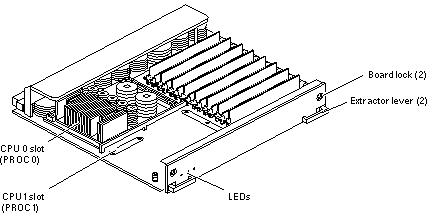
The CPU/Memory+ board (see Figure B-4) supports up to 2 CPU modules and 16 SIMMs.
Figure B-4 CPU/Memory+ Board

CPU Modules
Each CPU/Memory+ board has two sets of CPU connectors, marked PROC 0 and PROC 1.
The order in which you fill CPU slots is not critical. However, to optimize heat dissipation in the system:
-
Fill all PROC 0 locations on all CPU/Memory+ boards before filling any PROC 1 locations. To receive the maximum quantity of diagnostic information, fill PROC 0 on board 3.
-
After all PROC 0 locations are filled, you may begin filling the PROC 1 locations, again starting from the lowest slot number to the highest.
The Table B-1 table shows where five CPU modules are installed on three CPU/Memory+ boards (example only). Two board slots (1 and 9) do not have CPU/Memory+ boards installed because slot 1 is reserved for an I/O+ board, and in this example, slot 9 has a filler panel installed.
Table B-1 Five CPUs on Three Boards|
Board Slot Number |
CPU Slot PROC 0 |
CPU Slot PROC 1 |
|---|---|---|
|
1 - Reserved, I/O+ board |
||
|
3 |
in |
in |
|
5 |
in |
in |
|
7 |
in |
|
|
9 - Filler panel installed |
||
System Master
The board slots are interchangeable. A system master board is selected for the duration of POST and OBP testing to control the testing processes. The system master is normally the lowest-numbered slot containing a board with a functional CPU. After the tests are finished, the board slots are again fully equivalent.
SIMMs
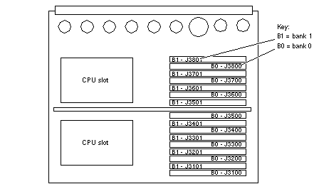
The CPU/Memory+ board has 16 slots for SIMMs, organized as two banks of eight SIMMs.
Slot Locations
SIMMs must be installed in full banks of eight. Figure B-5 shows the slot numbers for bank 0 and bank 1.
Figure B-5 SIMM Slot Locations

SIMM Selection
The JEDEC standard 3.3 volt SIMMs are available in 8, 32, or 128 Mbyte capacities. All are 168-pin SIMMs.
Do not mix different capacities in a bank.
- © 2010, Oracle Corporation and/or its affiliates
