PCI Cards
Each PCI+ board can accommodate two PCI (short) cards. The PCI cards are plugged into receptacles on corresponding riser cards that are mounted on the PCI+ I/O board. The riser cards can be one of two voltage types, either 5.0V or 3.3V.
The voltage rating of a PCI card must match the rating of the riser card and connector on the board. The PCI bus connectors of PCI cards can be one of three possible types, those that can be used with 5.0V or 3.3V connector receptacles only, and those that can be used with either voltage type.
Sun PCI+ I/O boards are shipped with two 5.0V riser cards (installed) and two 3.3V riser cards (not installed). If you are switching to a 3.3V PCI card, you must replace the existing 5.0V riser card with the 3.3V riser card. See "Replacing Riser Cards".
Removing a PCI Card
-
Use the procedures in "Removing a Board" to remove the applicable I/O+ board.
Note -Some PCI cards may not utilize the standoffs provided for mounting.
-
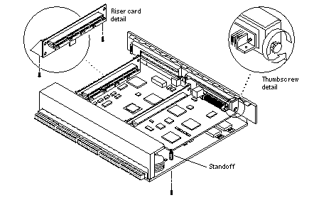
On the noncomponent side of the I/O+ board, loosen the locking standoff for the corresponding PCI card that is to be removed. See Figure 4-23.
Figure 4-23 PCI and Riser Card Removal

-
Loosen and then remove the thumbscrew on the component side of the I/O+ board next to the external PCI card connector. See Figure 4-23.
-
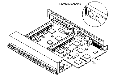
Refer to Figure 4-24 while removing the card as follows:
-
Grasp the card to be removed with your index fingers on either side of the card where it mates with the connector on the riser card (thumbs against the connector).
-
Loosen the card from the PCI bus connector and the catch mechanism by firmly pushing with your thumbs against the PCI bus connector, while grasping the card edge with the index fingers of both hands.
Figure 4-24 PCI Card Removal

-
-
Once the card is free of the PCI bus connector and the metal catch mechanism, remove the card from the I/O board. See Figure 4-24.
Replacing or Installing a PCI Card
-
Ensure that the voltage type of the PCI card you are replacing or installing matches the voltage type of the riser card, either 5.0V or 3.3V.
-
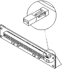
Verify that the JTAG Test Jumper is removed/disabled. See Figure 4-25.
Note -PCI+ I/O boards purchased from Sun Microsystems are shipped with the JTAG Test Jumper disabled or removed on both of the 5.0V riser cards installed on the board.
Figure 4-25 JTAG Test Jumper

-
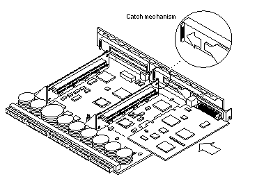
Align the PCI card so that the PCI bus connector mates with the PCI+ I/O board PCI bus connector, making sure that the external connector end of the card is retained on one side by the opening in the metal catch mechanism and the opposite end is properly aligned to accept the locking thumbscrew. See Figure 4-26.
Figure 4-26 PCI Card Installation/Replacement

-
Once the card is properly positioned (as described in step 3) and seated properly to the PCI+ board PCI Bus connector, tighten the locking thumbscrew.
Note -Some PCI cards may not utilize the nylon standoffs provided for mounting.
-
Ensure that the standoff is positioned to capture the edge of the PCI card, and then tighten the screw securing the standoff.
-
Use the procedures in "Installing a Board" to replace the PCI+ I/O board.
Replacing Riser Cards
-
Use the procedures in "Removing a Board" to remove the applicable I/O+ board.
-
If a PCI card is already installed in the slot designated for replacement of the riser card, remove the card as indicated in "Removing a PCI Card".
If there is no PCI card presently installed, proceed to Step 3.
-
Remove two screws securing the existing riser card to the PCI+ I/O board (see Figure 4-23) and remove the riser card.
-
Secure the new riser card onto the PCI+ I/O board using the two screws removed in Step 3.
-
If a PCI card was removed in Step 2, replace the card as indicated in the "Replacing or Installing a PCI Card".
Verifying Installation
After the PCI+ I/O board and any PCI cards are installed, and before booting the system, verify installation by performing the following tasks. Refer to the Solaris 2.x Handbook for SMCC Peripherals manual or your Solaris documentation for detailed instructions.
-
Power on the system, and when the banner appears, press the Stop-A keys to interrupt the boot process and get the ok prompt.
-
Use the show-devs command to list the system devices.
You should see entries (similar to the entries in the example on the next page) for the PCI+ I/O board that you installed.
In the example, a PCI+ I/O board with two SunSwift(TM) PCI adapter cards has been installed in I/O+ board slot 1 of a Sun Enterprise 3500 system. To find the device path for your specific device, refer to the documentation that came with your PCI card.
If you do not see your new device(s) listed, make sure the PCI+ I/O board and any PCI cards are properly seated, and reinstall the board or cards, if necessary.
Also verify that the JTAG Test Jumper on the PCI card is disabled or removed.
See "Replacing or Installing a PCI Card".
ok show-devs
.
.
.
/pci@3,2000/pci@2
/pci@3,2000/pci@2/SUNW,isptwo@4 (identifies adapter SCSI interface)
/pci@3,2000/pci@2/SUNW,hme@0,1 (identifies adapter Ethernet interface)
/pci@3,2000/pci@2/pci108e,1000@0
/pci@3,2000/pci@2/SUNW,isptwo@4/st
/pci@3,2000/pci@2/SUNW,isptwo@4/sd
/pci@3,3500/SUNW,isptwo@3 (identifies board SCSI interface)
.
.
.
/pci@2,2000/pci@2
/pci@2,2000/pci@2/SUNW,isptwo@4 (identifies adapter SCSI interface)
/pci@2,2000/pci@2/SUNW,hme@0,1 (identifies adapter Ethernet interface)
/pci@2,2000/pci@2/pci108e,1000@0
/pci@2,2000/pci@2/SUNW,isptwo@4/st
/pci@2,2000/pci@2/SUNW,isptwo@4/sd
/pci@2,3500/SUNW,hme@1,1 (identifies board Ethernet interface)
Flash PROM
The Sun Enterprise 3500 system I/O+ board uses flash PROMs. Flash PROMs may be reprogrammed and can be updated to the latest firmware code. Refer to the Sun Enterprise 6x00/5x00/4x00/3x00 System Flash PROM Programming Guide for this procedure.
Diagnostics Testing
For PCI+ I/O board PCI card diagnostics testing, refer to the SunVTS 2.1 User's Guide. Also, refer to the documentation that came with your PCI card for further diagnostic testing.
- © 2010, Oracle Corporation and/or its affiliates
