Disk Boards
A maximum of two Disk boards can be installed in Enterprise 6500 systems; four Disk boards can be installed in Enterprise 5500/4500 systems.
Note -
Disk boards can be installed only in slots 14 and 15 in Enterprise 6500 systems, and slot 15 must be used when installing only one Disk board.
Each Disk board contains a fast and wide single-ended SCSI chain with sockets for two disks. There are three status and two activity LEDs; each activity LED is driven directly by a disk drive.
Removing a Board
Removing a Board from a Powered-On System
Remove a board from a powered-on system only after the ASR software has disabled the board. If a board has not been disabled by the ASR software, then the operating system should be halted and the system powered off prior to board removal. See Chapter 11, Powering Off and On , then "Removing a Board from a Powered-Off System".
-
Ensure that the board has been disabled by the ASR software. See "Hot-Plug Feature".
Once disabled by ASR, one of two results occur:
-
The three LEDs on the board are not lit (board has no power)
-
The outer two green LEDs are not lit and the middle yellow LED is lit (board in low power mode).
Note -System software operates such that the LED pattern described is the same for a board that is component side-down (installed in front of card cage) or component-side up (installed in rear of card cage).
-
-
Unfasten any cable connectors from the front panel and set them aside.
Label cables to identify them for reconnection later.
-
Use a Phillips #1 screwdriver to mechanically release the board from the system card cage.
Insert the screwdriver into each quarter-turn access slot (the slots are located on the left and right sides of the board's front panel) and then turn a quarter turn so that the arrow points to the unlocked position (Figure 5-4).
Figure 5-4 Unlocking and Locking Quarter-Turn Access Slots

-
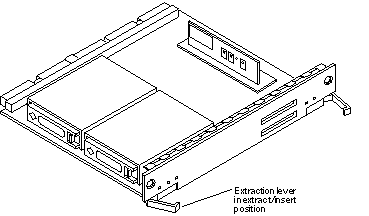
Pull the ends of both extraction levers outward simultaneously to unseat the board centerplane connector from the centerplane receptacles (Figure 5-5).
Figure 5-5 Disk Board

-
If a board is not immediately replaced, a filler panel or a load board (for Enterprise 6500 systems only) must be installed in its place.
Removing a Board from a Powered-Off System
-
Use a Phillips #1 screwdriver to mechanically release the board from the system card cage.
Insert the screwdriver into each quarter-turn access slot (the slots are located on the left and right sides of the board's front panel) and then turn a quarter turn so that the arrow points to the unlocked position (Figure 5-4).
-
Unfasten any cable connectors from the front panel and set them aside.
Label cables to identify them for reconnection later.
-
Pull the ends of both extraction levers outward simultaneously to unseat the board from the centerplane receptacles.
See Figure 5-5.
Installing a Board
Board Slot Selection
Note -
Logically there is no difference between the board slots in the front or rear of the card cage, and each slot can accept any board type. It is suggested that CPU/Memory+ boards be installed in the front slots, and I/O+ and Disk boards be installed in the rear slots because of cabling. Should the need arise, however, any of these three board types can be placed in any of the numbered board slots, with these exceptions: Slot 1: Slot 1 should be used by the first I/O+ board because it is the only slot connected to the onboard SCSI devices. Slots 14 and 15: In Enterprise 6500 systems, Disk boards are supported only in these two slots.
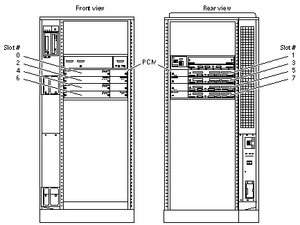
The first CPU/Memory+ board is placed in slot 0, followed sequentially by all remaining even numbered slots. If there are boards remaining, they can be installed sequentially in odd numbered slots, if available, in the system rear (with the exception of slot 1 as noted above). See Figure 5-6.
Other than the slot 1 exception, a Disk board can be placed in any of the numbered board slots in Enterprise 5500/4500 systems. Use only slot 14 and slot 15 in Enterprise 6500 systems, and you must use slot 15 if only one Disk board is installed.
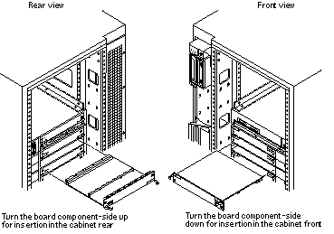
For boards being placed in the rear of the system, ensure that the component side is up. If the boards are placed in the front of the system, ensure that the component side is down (Figure 5-7).
Figure 5-6 Enterprise 5500/4500 Board Locations

Cooling and Power Issues
There should be one power/cooling module (PCM) for every two boards to adhere to cooling and power requirements. The PCMs must be installed adjacent to populated board slots to ensure the fan in the PCM can cool the respective boards.
Note -
All empty board slots in Enterprise 4500 or 5500 systems must have a filler panel installed to ensure proper cooling. All empty slots in Enterprise 6500 systems must have load boards installed.
Inserting a System Board
-
Carefully insert the board (component side down if in front; component side up if in the rear) in the proper slot in the card cage, ensuring that the board does not slip out of the left and right card guides (Figure 5-7).
Figure 5-7 Board Replacement

-
Ensure that both extraction levers are in the insert position (arrow pointing outward) and that the quarter-turn access slots are unlocked (arrow indicates unlocked position) as you slide the board toward the centerplane receptacles.
See Figure 5-4 and Figure 5-5. The board will not seat fully unless the levers are in this starting position and both quarter-turn access slots are unlocked.
 Caution -
 DO NOT FORCE any board into a slot; this can cause damage to the board and system. The board should insert and seat smoothly. If it binds, remove the board and inspect the card cage slot for any obvious obstructions. Also inspect both the board and the centerplane for bent pins or other damage.
-
Push the board into the card cage, then simultaneously press both extraction levers to seat the board on the centerplane.
Pushing both levers simultaneously avoids twisting the board and bending the connector pins, and mates the board centerplane connector to the matching receptacle on the centerplane. Do not press on board front panel to seat it--doing so will damage the connector pins.
-
Mechanically lock the board to the system chassis by inserting a Phillips #1 screwdriver into each quarter-turn access slot and then turning to the locked position.
See Figure 5-4.
-
Connect the Disk board to a SCSI Host Adapter (on-board or SBus card).
The Disk board kit includes an 80-cm fast-wide SCSI cable. If the Disk board is installed on the opposite side of the card cage from the SCSI Host Adapter, you must use a 2-meter cable, part number 530-1885 (sold separately).
-
If the Disk board is the last (or only) board in the SCSI chain, terminate the SCSI out connector on the disk board.
The Disk board kit includes a fast-wide SCSI terminator, part number 150-2267.
-
Replace or connect all other necessary cables to the fronts of the boards.
-
Once the Disk board has been installed, a message similar to the following will be displayed on the monitor (if the system is powered on):
Example depicts screen output when a new Disk board has been hot-plugged into slot 6 of an operating Enterprise system:
NOTICE: Disk Board Hotplugged into Slot 6
NOTICE: Board 6 is ready to remove
This screen output indicates that the board has been detected by the system and is in the low power mode. Additionally, any subsequent prtdiag(1M) output would include information for board slot 6. Again, note that the system will not use the new board until the system is rebooted.
-
Reboot the system now or schedule a later time to reboot when system disruption will be minimized.
Cabling Issues for Enterprise 6500 Systems
Slot 15 installation
-
Use an 80-cm SCSI cable to connect the Disk board to the SCSI Host Adapter (onboard or SBus card).
-
Install a SCSI terminator on the disk board if it is the last (or only) board in the SCSI chain.
Slot 14 installation
-
Connect the Disk board to the SCSI Host Adapter (onboard or SBus card):
-
If an I/O+ board is installed in the front, use an 80-cm SCSI cable to connect the Disk board to the SCSI Host Adapter.
-
If all I/O+ boards are installed in the rear, use a 2-meter SCSI cable (sold separately) to connect the Disk board to the SCSI Host Adapter. Route the cable down the side of the card cage, through the cable pass in the cabinet.
-
-
Install a SCSI terminator on the disk board if it is the last (or only) board in the SCSI chain.
Disk Drives
Removing a Disk Drive
-
Use the procedures described in, "Removing a Board", To remove the applicable Disk board.
-
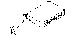
Unlatch and open the ejector drive retainer on the drive to be replaced (Figure 5-8).
Using the extended drive retainer as a handle pull the drive straight out to disengage it from the board mating receptacle and the drive mounting bracket.
Figure 5-8 Disk Drive with Ejector Drive Retainer Open

-
If a new drive is to be installed, proceed to the next section.
If the drive is not to be replaced, replace the Disk board as described in "Installing a Board".
Installing a Disk Drive
-
Inspect the shipping container upon receipt of your drive, and look for evidence of damage.
If the carrier's agent is not present when the container is opened, and the contents are damaged, keep all contents and packing materials for the agent's inspection.
-
If there is no evidence of damage, carefully remove the drive from the shipping container.
Save the carton and the packing material for possible later use.
-
Place the antistatic mat on a table or work surface.
-
Attach a grounding wrist strap.
Refer to the documentation that came with your ESD kit.
-
Remove the disk drive from its protective packaging.
Hold the disk drive by the edges, near the middle of the drive. Keep the drive vertical until you lay it on the ESD mat.
-
Place it on the antistatic mat with the component side of the disk drive controller cards facing up.
-
Unlatch and then open the ejector drive retainer for the drive being replaced or installed (Figure 5-8).
-
Using the drive retainer as a handle, slide the drive in and then seat it to the board connector receptacle.
Close and latch the ejector drive retainer.
-
SCSI IDs for disk drives on Disk boards are selected on the Disk board.
See Appendix C, SCSI Devices to select the SCSI ID for the disk drive.
-
Check that the ejector drive retainers on both disk drives are closed, latched in place, and do not extend past the edge of the board.
If an ejector drive retainer extends past the edge of the Disk board or is not fully closed, the disk drive connector is not joined with the Disk board connector. Do the following:
-
Use the unlatched drive retainer to unseat the drive from the board connector receptacle and slide it out an inch or two.
-
Check that the connectors are not broken and that nothing blocks the joining of these two connectors.
If there is a problem, put the disk drive back into its protective packaging, and contact your service representative.
Note -Save the antistatic shipping bag and other original packing. You will need these materials when transporting the disk drive.
-
-
Terminate the SCSI-out connector, if necessary.
The SCSI-out connector on Disk boards that are not daisy chained to an additional device must be terminated with a SCSI terminator. See Figure 5-3.
Note -The last or only disk board in a system must have the SCSI out connector terminated with a fast-wide SCSI terminator, part number 150-2267.
-
Replace the Disk board as described in "Installing a Board".
- © 2010, Oracle Corporation and/or its affiliates
