Enterprise 6500/5500 Systems
System Cabinet Fan Tray Assembly
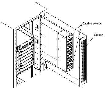
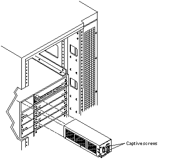
You must remove the fan tray screen (Figure E-1) to reach the assembly.
Note -
There is also a fan tray in the card cage ("Fan Tray Assembly, 200/240V") and one fan in the media tray.
Removing the Fan Tray Screen
Figure E-1 Replacing the Fan Tray Assembly in the Enterprise 6500/5500 Systems
-
Loosen the four screws on the left and the four screws on the right of the fan tray screen.
It is not necessary to completely remove these four screws.
-
Lift the screen up until the slotted screw holes clear the screw heads, and set it aside.
Removing the Fan Tray Assembly
-
Disconnect the power cable and fan cable assembly.
-
Loosen the two captive screws on the fan tray assembly (Figure E-1).
-
Tilt the fan tray assembly back slightly so that it clears the top of the cabinet.
-
Remove the fan tray assembly.
Replacing the Fan Tray Assembly
-
Tilt the fan tray assembly inward and lower it behind the upper sequencer bracket.
-
Push the fan tray into the cabinet until the fan tray cannot be inserted any further.
-
Tighten the two captive screws at the top and bottom of the fan tray (Figure E-1).
-
Replace the power cable and fan fail cable.
Replacing the Fan Tray Screen
-
Replace the screen so that the slotted screw holes clear the screw heads.
-
Tighten the four screws on the left and the four screws on the right.
AC Power Cable
Removing the AC Power Cable
-
Power off the system.
See the power off instructions in Chapter 11, Powering Off and On .
-
Disconnect the AC power cable from the power connector.
-
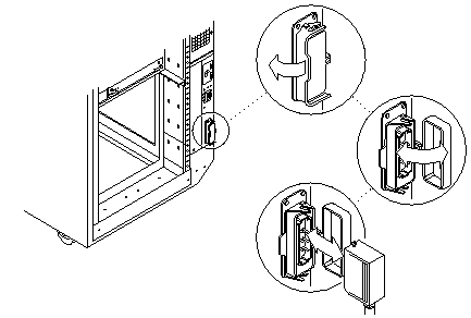
Push back and release the latch (Figure E-2) attaching the power cable to the power connector .
Figure E-2 Opening the Power Connector Cover
-
Unplug the AC power cable.
Close the power connector cover.
Replacing the AC Cable Assembly
-
Pull back the power connector cover (Figure E-2) to expose the power connector.
-
Connect the AC power cable into the power connector.
-
Pull the latch over the AC power cable.
-
Connect the AC power cable to the wall socket.
-
Power on the Enterprise system.
See the power on instructions in Chapter 11, Powering Off and On .
Universal System Cabinet Power Sequencer
Removing the Power Sequencer
-
Completely power off the Enterprise system.
See the power off instructions in Chapter 11, Powering Off and On .
-
Remove the power cord assembly from the back of the power sequencer.
See "AC Power Cable", for information on removing the power cord.
-
Remove the side panel closest to the power sequencer.
See Chapter 12, Preparing for Service, for information on removing the side panel.
-
Disconnect all the cable assemblies from the front of the power sequencer.
Reach through the space uncovered by the side panel to disconnect these cable assemblies.
-
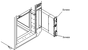
Remove the two screws at the top of the power sequencer (Figure E-3).
Figure E-3 Replacing the Power Sequencer
-
Remove the two screws at the bottom of the power sequencer.
-
Tilt the power sequencer slightly so that it clears the top and lift it up and out of the cabinet.
You may use the power inlet to obtain a grip on the power sequencer.
Replacing the Power Sequencer
-
Tilt the power sequencer inward and seat the bottom in the cabinet opening.
There are two retainers at the bottom of the power sequencer which rest on the sheet metal at the bottom of the cabinet opening.
-
Tilt the power sequencer so that it is flush against the cabinet.
-
Replace the two screws at the bottom of the power sequencer (Figure E-3).
-
Replace the two screws at the top of the power sequencer.
-
Connect all the cable assemblies to the front of the power sequencer.
Reach through the space uncovered by the side panel to replace these cable assemblies.
-
Replace the side panel closest to the power sequencer.
See Chapter 12, Preparing for Service, for information on replacing the side panel.
-
Replace the power cord assembly at the back of the power sequencer.
See "AC Power Cable", for information on replacing the power cord.
-
Power on the Enterprise system.
See the power on instructions in Chapter 11, Powering Off and On .
Media Tray
Replacing the Media Tray Fan
The media tray contains one fan. To replace this fan:
-
Remove the left side panel.
See Chapter 12, Preparing for Service, for instructions.
-
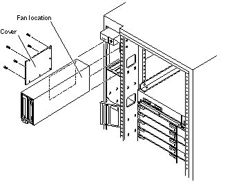
Remove the side cover (Figure E-4) from the media tray.
Remove seven screws from the cover to reach the fan.
Note -It is not necessary to remove the media tray from the cabinet.
Figure E-4 Replacing the Fan in the Media Tray in the Enterprise 6500/5500 Systems
-
Pull the power cable off the fan.
-
Remove the four screws from the fan and replace the fan.
-
Reverse steps 1 through 3 to complete the procedure.
Removing the Cable Assemblies
-
Completely power off the Enterprise system.
See the power off instructions in Chapter 11, Powering Off and On .
-
Remove the key from the key switch.
-
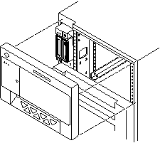
Grasp the front bezel on both sides at the top and pull it out far enough to disengage the ball studs (Figure E-5).
 Caution -
 To prevent breakage, do not grasp the bezel by the bottom edge.
Figure E-5 Removing the Front Bezel
-
Remove the bezel and set it aside.
-
Open the hinged door on the front panel by pulling the right side of the upper door panel.
The door is hinged on the left side and swings open if pulled firmly.
-
Remove the side panel closest to the key switch assembly.
See Chapter 12, Preparing for Service, for information on removing the side panel.
-
Disconnect the media tray power assembly and/or data cable assembly from the back of the media tray.
-
Pull the cable assembly through the opening in the cabinet to the front of the card cage.
The cable assembly runs through the front of the fan tray shelf and the system cabinet pillar to the SCSI adapter assembly.
-
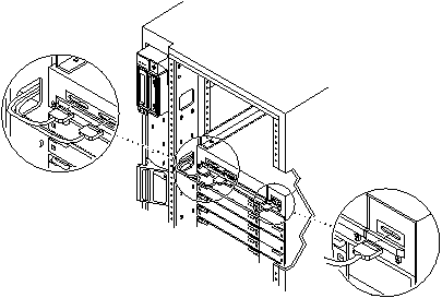
Disconnect the cable assembly from the front of the SCSI adapter assembly and remove the cable assembly (Figure E-6).
Figure E-6 Removing the Cable Assemblies From the Front of the SCSI Adapter Tray
Replacing the Cable Assembly
-
Connect the media tray power and data cable assembly to the back of the media tray.
-
Pull the cable assembly through the opening in the cabinet to the front of the card cage.
The cable assembly runs through the front of the fan tray shelf and the system cabinet pillar to the SCSI adapter assembly.
-
Connect the cable assembly into the front of the SCSI adapter assembly (Figure E-6).
-
Replace the side panel.
See Chapter 12, Preparing for Service, for information on replacing the side panel.
-
Close the front door.
-
Place the front bezel against the cabinet with the ball studs aligned with the catches on the bezel.
Tap or press both sides of the bezel into place (Figure E-5).
-
Power on the Enterprise system.
See the power on instructions in Chapter 11, Powering Off and On .
Key Switch Assembly
Removing the Key Switch Assembly
-
Power off the Enterprise system.
See the power off instructions in Chapter 11, Powering Off and On .
-
Remove the key from the key switch.
-
Remove the top front panel by grasping the bezel on both sides and pulling the bezel away from the ball studs (Figure 12-1).
-
Remove the left side panel.
See Chapter 12, Preparing for Service, for instructions.
-
Disconnect the power and data cable assemblies from the back of the media tray.
-
Remove the two screws that attach the media tray to the flange on the side of the fan tray shelf (Figure E-7).
-
Disconnect the power cable from the fan in the media tray.
-
Disconnect the keyswitch cable.
-
Loosen and remove the tie wrap from fan cable.
-
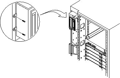
Remove the two screws (Figure E-8) that hold the media tray.
-
Remove the media tray and set it aside.
Figure E-7 Removing the Two Screws that Attach the media tray to the Flange
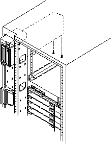
Figure E-8 Removing the Two Screws that Attach the media tray to the Cabinet Pillar
-
Disconnect the cable from the back of the key switch assembly.
-
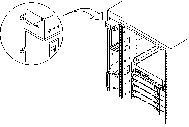
Remove the screw on the left side that attaches the key switch assembly to the cabinet pillar (Figure E-9).
Figure E-9 Removing the Screw from the Left Pillar
-
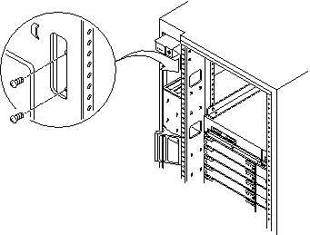
Remove the two screws on the right side that attach the key switch assembly to the cabinet pillar.
You can access the two screws through the space previously occupied by the media tray (Figure E-10).
Figure E-10 Removing the Two Screws from the Right Pillar
-
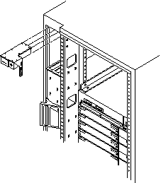
Carefully remove the key switch assembly from the cabinet.
Pull out the right side first and gently rock the assembly until the left flange clears the cabinet (Figure E-11).
Figure E-11 Replacing the Key Switch Assembly in the Enterprise 6500/5500 Systems
Replacing the Key Switch Assembly
-
Insert the key switch assembly into the cabinet until it is seated properly.
The key switch assembly is seated properly when the screw holes align with the cabinet pillar (Figure E-11).
-
Replace the two screws on the right side that attach the key switch assembly to the cabinet pillar.
You can access the two screws through the space previously occupied by the media tray (Figure E-10).
-
Replace the screw on the left side that attaches the key switch assembly to the cabinet pillar (Figure E-9).
-
Connect the key switch cable assembly into the back of the key switch assembly.
-
Replace the media tray into the cabinet using the support system cabinet CD shelf as a guide.
When seated properly, the media tray is flush with the key switch assembly in the cabinet.
-
Replace the two screws that attach the media tray to the cabinet pillar (Figure E-8).
-
Replace the two screws that attach the media tray to the flange on the bottom of the fan tray shelf (Figure E-7).
-
Connect the media tray power and data cable assemblies into the back of the media tray.
-
Replace the fan tray shelf cover.
Replace the 10 screws and attach the cover to the cabinet.
-
Replace the side panel closest to the key switch assembly.
See Chapter 12, Preparing for Service, for information on replacing the side panel.
-
Power on the Enterprise system.
See the power on instructions in Chapter 11, Powering Off and On .
SCSI Tape Adapter PCS Assembly
Removing the SCSI Adapter Assembly
-
Completely power off the Enterprise system.
See the power off instructions in Chapter 11, Powering Off and On .
-
Disconnect the two cable assemblies from the front of the SCSI adapter assembly (Figure E-6).
-
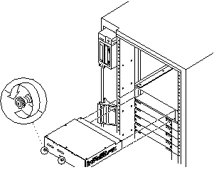
Loosen the three captive screws on the bottom that secure the SCSI adapter assembly to the cabinet (Figure E-12).
Figure E-12 Removing the SCSI Tape Adapter PCS Assembly in the Enterprise 6500/5500 Systems
-
Pull and slowly remove the SCSI adapter assembly from the cabinet.
Replacing the SCSI Adapter Assembly
-
Carefully insert the SCSI adapter assembly into the front of the Enterprise system.
 Caution -
 DO NOT FORCE the SCSI adapter assembly into the slot; this can cause damage to the assembly and system.
The SCSI adapter assembly should insert and seat smoothly. If it binds, remove it, and inspect the slot for any obvious obstructions. Do not damage the springfingers at the bottom of the assembly.
-
Tighten the three captive screws on the bottom that secure the SCSI adapter assembly to the cabinet (Figure E-12).
-
Connect the two cable assemblies to the front of the SCSI adapter assembly (Figure E-6).
-
Power on the Enterprise system.
See the power on instructions in Chapter 11, Powering Off and On .
Key Switch Adapter Assembly
Removing the Key Switch Adapter Assembly
-
Completely power off the Enterprise 6500 system.
See the power off instructions in Chapter 11, Powering Off and On .
-
Disconnect the cable assembly from the front of the key switch adapter assembly.
-
Loosen the two captive screws on the bottom that secure the key switch adapter assembly to the cabinet.
-
Pull and slowly remove the key switch adapter assembly from the cabinet.
Replacing the Key Switch Adapter Assembly
-
Carefully insert the key switch adapter assembly into the front of the Enterprise 6500 system.
 Caution -
 DO NOT FORCE the key switch adapter assembly into the slot; this can cause damage to the assembly and system.
The key switch adapter assembly should insert and seat smoothly. If it binds, remove it, and inspect the slot for any obvious obstructions. Do not damage the springfingers at the bottom of the assembly.
-
Tighten the two captive screws on the bottom that secure the key switch adapter assembly to the cabinet.
-
Connect the cable assembly to the front of the key switch adapter assembly.
-
Power on the Enterprise 6500 system.
See the power on instructions in Chapter 11, Powering Off and On .
Fan Tray Assembly, 200/240V
Removing the Fan Tray Assembly
-
Power off the system.
See the power off instructions in Chapter 11, Powering Off and On .
-
Locate the fan tray assembly (Figure E-13) at the back of the card cage.
The fan tray includes two connectors and a switch.
Figure E-13 Removing the 200/240V Fan Tray Assembly
-
Disconnect the cables from the fan tray assembly.
-
Loosen the two captive screws on the left side that secure the fan tray assembly to the cabinet.
-
Pull and slowly remove the fan tray assembly from the cabinet.
Replacing the Fan Tray Assembly
-
Carefully insert the fan tray assembly into the cabinet.
Viewed from the rear of the system, the fan tray is on the left side of the cabinet (Figure E-13).
 Caution -
 DO NOT FORCE the fan tray assembly into the slot; this can cause damage to the fan tray assembly and system.
The fan tray assembly should insert and seat smoothly. If it binds, remove it, and inspect the slot for any obvious obstructions. Do not damage the springfingers at the bottom of the fan tray assembly.
-
Tighten the two captive screws to secure the fan tray in place.
-
Reconnect the cables.
-
Power on the Enterprise system.
See the power on instructions in Chapter 11, Powering Off and On .
Centerplane
Removing the Centerplane
-
Completely power off the Enterprise system.
See the power off instructions in Chapter 11, Powering Off and On .
-
Remove the front bezel, front door and rear screen panel.
See Chapter 12, Preparing for Service, for information on removing these assemblies.
-
Remove any assemblies above and below the Enterprise system.
Refer to the respective service manuals for further information.
-
Remove all the boards and power supplies.
See Chapters 3-6 for information on removing the boards and Chapter 7, Power Supplies, for information on removing power supplies.
-
Remove the SCSI adapter assembly, the key switch adapter assembly, and the 200/240V fan tray assembly.
See "SCSI Tape Adapter PCS Assembly", "Key Switch Adapter Assembly", and "Fan Tray Assembly, 200/240V" for information on removing these assemblies.
-
Disconnect any remaining cables from the Enterprise system main cabinet.
-
Remove the two screws on each side of the system cabinet that attach the top rails to the system cabinet.
-
Loosen the four screws on each side of the system cabinet that attach the top rails to the main chassis.
-
Remove the top rails and set them aside.
Guide the four screws through the key slots in each top rail.
-
Remove the four screws on each side of the system cabinet that attach the bottom rails to the main chassis.
 Caution -
 Use care when removing the Enterprise system chassis. It weighs approximately 100 pounds.
-
Carefully slide the Enterprise system chassis out toward the front and place it front side down onto a surface.
-
Remove the screws around the center of the main chassis.
-
For the Enterprise 6500 system, there are a total of 32 screws, 8 per side.
-
For the Enterprise 5500 system, there are a total of 26 screws.
-
-
Lift and remove the rear chassis and set it aside.
-
Remove the screws that hold the centerplane to the front chassis.
-
For the Enterprise 6500 system, there are a total of 27 screws, 20 screws around the side and 7 in the interior section.
-
For the Enterprise 5500 system, there are a total of 20 screws.
Note -Remember the proper orientation of the centerplane when removing it from the front chassis.
-
-
Lift the centerplane out and set it aside.
Replacing the Centerplane
-
Place the centerplane in the front chassis.
Be sure the centerplane has the proper orientation when placed in the front chassis.
-
Replace the screws that hold the centerplane to the front chassis.
-
For the Enterprise 6500 system, there are a total of 27 screws, 20 screws around the side and 7 in the interior section.
-
For the Enterprise 5500 system, there are a total of 20 screws.
-
-
Place the rear chassis on the front chassis.
-
Replace the screws around the center of the main chassis.
-
For the Enterprise 6500 system, there are a total of 32 screws, 8 per side.
-
For the Enterprise 5500 system, there are a total of 26 screws.
 Caution -
 Use care when lifting the Enterprise system chassis. It weighs approximately 100 pounds.
-
-
Slide the main chassis into the system cabinet.
Use the bottom rails as a guide.
-
Replace the four screws on each side of the system cabinet that attach the bottom rails to the main chassis.
-
Replace the top rails.
-
Replace the SCSI adapter assembly, the key switch adapter assembly, and the 200/240V fan tray assembly.
See "SCSI Tape Adapter PCS Assembly", "Key Switch Adapter Assembly", and "Fan Tray Assembly, 200/240V" for information on replacing these assemblies.
-
Replace all the boards and power supplies.
See Chapters 3-6 for information on replacing the boards and Chapter 7, Power Supplies, for information on replacing power supplies.
-
Connect any remaining cables to the Enterprise system main cabinet.
-
Replace any assemblies above and below the Enterprise system.
Refer to the respective service manuals for further information.
-
Replace the front bezel, front door and rear screen panel.
See Chapter 12, Preparing for Service, for information on replacing these assemblies.
-
Power on the Enterprise system.
See the power on instructions in Chapter 11, Powering Off and On .
- © 2010, Oracle Corporation and/or its affiliates
