| C H A P T E R 2 |
|
System Overview |
This chapter introduces you to the Sun Fire V490 server and describes some of its features.
The following information is covered in this chapter:
The Sun Fire V490 system is a high-performance, shared memory, symmetric multiprocessing server that supports up to four UltraSPARC® IV or UltraSPARC® IV+ processors.
The system, which is mountable in a 4-post cabinet or 2-post rack, measures 8.75 inches (5 rack units - RU) high, 17.5 inches wide, and (without its plastic bezel) 24 inches deep (22.225 cm x 44.7 cm x 60.96 cm). The system weighs between 79 and 97 lbs (35.83 to 44 kg).
Processing power is provided by up to two dual CPU/Memory boards. Each board incorporates:
For information about available processor speeds, memory capacity, and supported combinations of processors, refer to the Sun Fire V490/V890 CPU/Memory Module Configuration Guide, available at:
http://www.sun.com/products-n-solutions/hardware/docs/Servers
A fully configured Sun Fire V490 system includes a total of four processors residing on two CPU/Memory boards. For more information, refer to About the CPU/Memory Boards.
Total system memory is shared by all processors in the system. For more information about system memory, refer to About the Memory Modules.
System I/O is handled by four separate Peripheral Component Interconnect (PCI) buses. These industry-standard buses support all of the system's on-board I/O controllers in addition to six slots for PCI interface cards. Four of the PCI slots operate at a 33-MHz clock rate, and two slots operate at either 33 or 66 MHz. All slots comply with PCI Local Bus Specification Revision 2.1. For additional details, refer to About the PCI Cards and Buses.
Internal disk storage is provided by up to two 1-inch, hot-pluggable, Fibre Channel-Arbitrated Loop (FC-AL) disk drives. Both single-loop and dual-loop configurations are supported. The basic system includes an FC-AL disk backplane that accommodates disks of different capacities. In addition, an external FC-AL port exists on the system's back panel. For additional details, refer to Locating Back Panel Features.
The backplane provides dual-loop access to each of the FC-AL disk drives. One loop is controlled by an on-board FC-AL controller integrated into the system centerplane. The second loop is controlled by a PCI FC-AL host adapter card (available as a system option). This dual-loop configuration enables simultaneous access to internal storage via two different controllers, which increases available I/O bandwidth. A dual-loop configuration can also be combined with multipathing software to provide hardware redundancy and failover capability. Should a component failure render one loop inaccessible, the software can automatically switch data traffic to the second loop to maintain system availability. For more information about the system's internal disk array, refer to About FC-AL Technology, About the FC-AL Backplane, and About the FC-AL Host Adapters.
External multidisk storage subsystems and redundant array of independent disks (RAID) storage arrays can be supported by installing single-channel or multichannel PCI host adapter cards along with the appropriate system software. Software drivers supporting FC-AL and other types of devices are included in the Solaris OS.
The system provides two on-board Ethernet host PCI adapters, which support several modes of operations at 10, 100, and 1000 megabits per second (Mbps).
Additional Ethernet interfaces or connections to other network types can be provided by installing the appropriate PCI interface cards. Multiple network interfaces can be combined with multipathing software to provide hardware redundancy and failover capability. Should one of the interfaces fail, the software can automatically switch all network traffic to an alternate interface to maintain network availability. For more information about network connections, refer to How to Configure the Primary Network Interface and How to Configure Additional Network Interfaces.
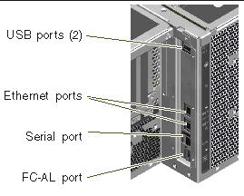
The Sun Fire V490 server provides a serial communication port, which you can access through an RJ-45 connector located on the system's back panel. For more information, refer to About the Serial Port.
The back panel also provides two Universal Serial Bus (USB) ports for connecting USB peripheral devices such as modems, printers, scanners, digital cameras, or a Sun Type-6 USB keyboard and mouse. The USB ports support both isochronous mode and asynchronous mode. The ports enable data transmission at speeds of
12 Mbps. For additional details, refer to About the USB Ports.
The local system console device can be either a standard ASCII character terminal or a local graphics console. The ASCII terminal connects to the system's serial port, while a local graphics console requires installation of a PCI graphics card, monitor, USB keyboard, and mouse. You can also administer the system from a remote workstation connected to the Ethernet or from the system controller.
Sun Remote System Control (RSC) software is a secure server management tool that lets you monitor and control your server over a serial line or over a network. RSC provides remote system administration for geographically distributed or physically inaccessible systems. RSC software works in conjunction with the system controller (SC) card included in all Sun Fire V490 servers.
The SC card runs independently of the host server, and operates off of 5-volt standby power from the system's power supplies. These features allow the SC to serve as a "lights out" management tool that continues to function even when the server operating system goes offline or when the server is powered off. For additional details, refer to About the System Controller (SC) Card.
The basic system includes two 1448-watt power supplies, each with two internal fans. The power supplies are plugged in directly to one power distribution board (PDB). One power supply provides sufficient power for a maximally configured system. The second power supply provides N+1 redundancy, allowing the system to continue operating should the first power supply fail. A power supply in a redundant configuration is hot-swappable, so that you can remove and replace a faulty power supply without shutting down the operating system or turning off the system power. For more information about the power supplies, refer to About the Power Supplies.
System reliability, availability, and serviceability (RAS) are enhanced by features that include hot-pluggable disk drives and redundant, hot-swappable power supplies. A full list of RAS features is in the section, About Reliability, Availability, and Serviceability Features.
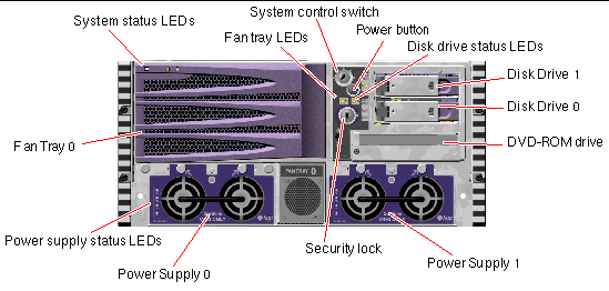
The illustration below shows the system features that you can access from the front panel. In the illustration, the media door (upper right) and the power supply access panel (bottom) are removed.

For information about front panel controls and indicators, refer to LED Status Indicators.
In addition to the security lock on the system's front panel, a top panel lock on the top of the system controls entry to both the PCI access panel and the CPU access panel. When the key is in the upright position, the media door is unlocked. However, even if the top panel lock is in the Locked position, thereby locking both the PCI and CPU access panels, you can still unlock the media door security lock and gain access to the disk drives, power supplies, and Fan Tray 0. If the media door is locked and the power supply access panel is in place, you will not be able to gain access to the power supplies, disk drives, and Fan Tray 0--even if the PCI access panel is unlocked.
|
Note - The same key operates the security lock, the system control switch (refer to System Control Switch), and the top panel lock for the PCI and CPU access panels. |
The standard system is configured with two power supplies, which are accessible from the front of the system. LED indicators display power status. Refer to LED Status Indicators for additional details.
Several LED status indicators on both the front and back panels provide general system status, alert you to system problems, and help you to determine the location of system faults.
At the top left of the system as you look at its front are three general system LEDs. Two of these LEDs, the system Fault LED and the Power/OK LED, provide a snapshot of the overall system status. The Locator LED helps you to locate a specific system quickly, even though it may be one of dozens or even scores of systems in a room. The front panel Locator LED is at the far left in the cluster. The Locator LED is lit by command from the administrator. For instructions, refer to How to Operate the Locator LED.
Other LEDs located on the front of the system work in conjunction with specific fault LED icons. For example, a fault in the disk subsystem illuminates the disk drive Fault LED in the center of the LED cluster that is next to the affected disk drive. Since all front panel status LEDs are powered by the system's 5-volt standby power source, Fault LEDs remain lit for any fault condition that results in a system shutdown.
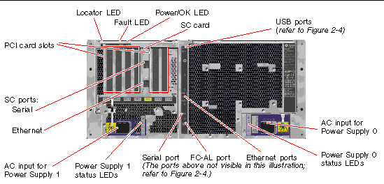
Locator, Fault, and Power/OK LEDs are also found at the upper-left corner of the back panel. Also located on the back panel are LEDs for the system's two power supplies and RJ-45 Ethernet ports.
Refer to FIGURE 2-1 and FIGURE 2-4 for locations of the front panel and back panel LEDs.
During system startup, LEDs are toggled on and off to verify that each one is working correctly.
The following tables list and describe the LEDs on the front panel: system LEDs, fan tray LEDs, and hard disk drive LEDs.
Listed from left to right, the system LEDs operate as described in the following table.
The following table describes the fan tray LEDs.
|
This amber LED lights when a fault is detected in the CPU fans. |
|
|
This amber LED lights when a fault is detected in the PCI fans. |
The following table describes the disk drive LEDs.
Further details about the diagnostic use of LEDs are discussed separately in the section, How to Isolate Faults Using LEDs.
The system Power button is recessed to prevent accidentally turning the system on or off. The ability of the Power button to turn the system on or off is controlled by the system control switch. Refer to the section, System Control Switch.
If the operating system is running, pressing and releasing the Power button initiates a graceful software system shutdown. Pressing and holding in the Power button for five seconds causes an immediate hardware shutdown.

|
Caution - Whenever possible, you should use the graceful shutdown method. Forcing an immediate hardware shutdown may cause disk drive corruption and loss of data. |
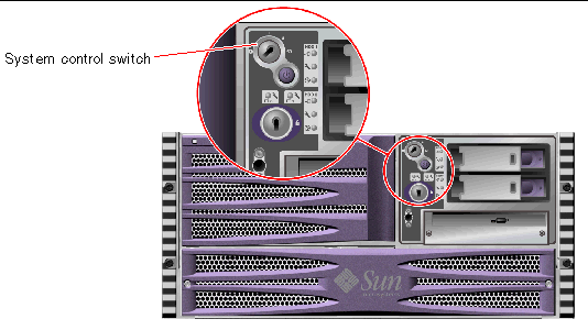
The four-position system control switch on the system's status and control panel controls the power-on modes of the system and prevents unauthorized users from powering off the system or reprogramming system firmware. In the following illustration, the system control switch is in the Locked position.

The following table describes the function of each system control switch setting.
The following figure shows the system features that you can access from the back panel.

Main system LEDs--Locator, Fault, and Power/OK--are repeated on the back panel. (Refer to TABLE 2-1, TABLE 2-2, and TABLE 2-3 for descriptions of front panel LEDs.) In addition, the back panel includes LEDs that display the status of each of the two power supplies and both on-board Ethernet connections. Two LEDs located on each Ethernet RJ-45 connector display the status of Ethernet activity. Each power supply is monitored by four LEDs.
Details of the diagnostic use of LEDs are discussed separately in the section,
How to Isolate Faults Using LEDs.
TABLE 2-5 lists and describes the Ethernet LEDs on the system's back panel.
TABLE 2-6 lists and describes the power supply LEDs on the system's back panel.
Also accessible from the back panel are:

Reliability, availability, and serviceability (RAS) are aspects of a system's design that affect its ability to operate continuously and to minimize the time necessary to service the system. Reliability refers to a system's ability to operate continuously without failures and to maintain data integrity. System availability refers to the percentage of time that a system remains accessible and usable. Serviceability relates to the time it takes to restore a system to service following a system failure. Together, reliability, availability, and serviceability features provide for near continuous system operation.
To deliver high levels of reliability, availability and serviceability, the Sun Fire V490 system offers the following features:
Sun Fire V490 hardware is designed to support hot-plugging of internal disk drives and hot-swapping of power supplies. With the proper software support, you can install or remove these components while the system is running. Hot-plug and
hot-swap technology significantly increases the system's serviceability and availability, by providing the ability to:
For additional information about the system's hot-pluggable and hot-swappable components--including a discussion of the differences between the two practices--refer to About Hot-Pluggable and Hot-Swappable Components.
The system features two hot-swappable power supplies, either of which is capable of handling the system's entire load. Thus, the system provides N+1 redundancy, allowing the system to continue operating should one of the power supplies or its AC power source fail. For more information about power supplies, redundancy, and configuration rules, refer to About the Power Supplies.
The Sun Fire V490 system features an environmental monitoring subsystem designed to protect against:
Monitoring and control capabilities reside at the operating system level as well as in the system's Boot PROM firmware. This ensures that monitoring capabilities remain operational even if the system has halted or is unable to boot.
The environmental monitoring subsystem uses an industry-standard Inter-Integrated Circuit (I2C) bus. The I2C bus is a simple two-wire serial bus, used throughout the system to allow the monitoring and control of temperature sensors, fans, power supplies, status LEDs, and the front panel system control switch.
Temperature sensors are located throughout the system to monitor the ambient temperature of the system and the temperature of several application-specific integrated circuits (ASICs). The monitoring subsystem polls each sensor and uses the sampled temperatures to report and respond to any overtemperature or undertemperature conditions.
The hardware and software together ensure that the temperatures within the enclosure do not stray outside predetermined "safe operation" ranges. If the temperature observed by a sensor falls below a low-temperature warning threshold or rises above a high-temperature warning threshold, the monitoring subsystem software lights the system Fault LED on the front status and control panel.
All error and warning messages are displayed on the system console (if one is attached) and are logged in the /var/adm/messages file. Front panel Fault LEDs remain lit after an automatic system shutdown to aid in problem diagnosis.
The monitoring subsystem is also designed to detect fan failures. The system features two fan trays, which include a total of five individual fans. If any fan fails, the monitoring subsystem detects the failure and generates an error message and logs it in the /var/adm/messages file, lights the appropriate fan tray LED, and lights the system Fault LED.
The power subsystem is monitored in a similar fashion. Polling the power supply status registers periodically, the monitoring subsystem indicates the status of each supply's DC outputs.
If a power supply problem is detected, an error message is displayed on the system console and logged in the /var/adm/messages file. Additionally, LEDs located on each power supply are illuminated to indicate failures.
To some, automatic system recovery (ASR) implies an ability to shield the operating system in the event of a hardware failure, allowing the operating system to remain up and running. The implementation of ASR on the Sun Fire V490 server is different. ASR on the Sun Fire V490 server provides for automatic fault isolation and restoration of the operating system following non-fatal faults or failures of these hardware components:
In the event of such a hardware failure, firmware-based diagnostic tests isolate the problem and mark the device (using the 1275 Client Interface, via the device tree) as either failed or disabled. The OpenBoot firmware then deconfigures the failed device and reboots the operating system. This all occurs automatically, as long as the Sun Fire V490 system is capable of functioning without the failed component.
Once restored, the operating system will not attempt to access any deconfigured device. This prevents a faulty hardware component from keeping the entire system down or causing the system to crash repeatedly.
As long as the failed component is electrically dormant (that is, it does not cause random bus errors or introduce noise into signal lines), the system reboots automatically and resumes operation. Be sure to contact a qualified service technician about replacing the failed component.
Multiplexed I/O (MPxIO), a feature found in the Solaris 8 Operating System, is a native multipathing solution for storage devices such as Sun StorEdge disk arrays. MPxIO provides:
For further details about MPxIO, refer to Multiplexed I/O (MPxIO). Also consult your Solaris documentation.
Sun Remote System Control (RSC) software is a secure server management tool that lets you monitor and control your server over a serial line or over a network. RSC provides remote system administration for geographically distributed or physically inaccessible systems. The RSC software works with the system controller (SC) card on the Sun Fire V490 system PCI riser board. The SC card provides an Ethernet connection to a remote console and a serial connection to a local alphanumeric terminal.
Once RSC is configured to manage your server, you can use it to run diagnostic tests, view diagnostic and error messages, reboot your server, and display environmental status information from a remote console.
RSC provides the following features:
For more details about system controller hardware, refer to About the System Controller (SC) Card.
For further information, refer to How to Monitor the System Using the System Controller and RSC Software and the Sun Remote System Controller (RSC) 2.2 User's Guide provided on the Sun Fire V490 Documentation CD.
To detect and respond to system hang conditions, the Sun Fire V490 system features a hardware watchdog mechanism--a hardware timer that is continually reset as long as the operating system is running. In the event of a system hang, the operating system is no longer able to reset the timer. The timer will then expire and cause an automatic externally initiated reset (XIR), eliminating the need for operator intervention. When the watchdog mechanism resets the system after sending information to the screen and depending upon the OBP variable, a core file might be created to give additional information.
|
Note - The hardware watchdog mechanism is not activated until you enable it. Refer to How to Enable the Watchdog Mechanism and Its Options for instructions. |
The XIR feature is also available for you to invoke manually, by way of your RSC console. You use the xir command manually when the system is absolutely hung and an L1-A (Stop-A) keyboard command does not work. When you issue the xir command manually by way of RSC, the system is immediately returned to the OpenBoot PROM ok prompt. From there, you can use OpenBoot commands to debug the system.
The system's dual-ported Fibre Channel-Arbitrated Loop (FC-AL) disk drives and dual-loop enabled FC-AL backplane may be combined with an optional PCI FC-AL host adapter card to provide for fault tolerance and high availability of data. This dual-loop configuration allows each disk drive to be accessed through two separate and distinct data paths, providing both increased bandwidth and hardware redundancy; that is, dual-loop configuration provides the ability to sustain component failures in one path by switching all data transfers to an alternate path.
The FC-AL subsystem is described in greater detail in:
By attaching one or more external storage devices to the Sun Fire V490 server, you can use a software RAID application, such as Sun StorEdge , to configure system disk storage in a variety of different RAID levels. Configuration options include RAID 0 (striping), RAID 1 (mirroring), RAID 0+1 (striping plus mirroring), RAID 1+0 (mirroring plus striping), and RAID 5 (striping with interleaved parity). You choose the appropriate RAID configuration based on the price, performance, and reliability and availability goals for your system. You can also configure one or more drives to serve as "hot spares" to fill in automatically for a defective drive in the event of a disk failure.
For more information, refer to About Volume Management Software.
Error correcting code (ECC) is used on all internal system data paths to ensure high levels of data integrity. All data that moves between processors, memory, and PCI bridge chips have end-to-end ECC protection.
The system reports and logs correctable ECC errors. A correctable ECC error is any single-bit error in a 128-bit field. Such errors are corrected as soon as they are detected. The ECC implementation can also detect double-bit errors in the same 128-bit field and multiple-bit errors in the same nibble (4 bits).
In addition to providing ECC protection for data, the system offers parity protection on all system address buses. Parity protection is also used on the PCI and SCSI buses, and in the UltraSPARC IV processors' internal and external caches.
Copyright © 2004, Sun Microsystems, Inc. All Rights Reserved.