| C H A P T E R 3 |
|
Hardware Configuration |
This chapter provides hardware configuration information for the Sun Fire V490 server.
The following topics are covered in this chapter:
For configuration information about network interfaces, refer to:
In a Sun Fire V490 system, the FC-AL disk drives are hot-pluggable components and the power supplies are hot-swappable. (No other component of the system is either hot-pluggable or hot-swappable.) Hot-pluggable components are those that you can install or remove while the system is running, without affecting the rest of the system's capabilities. However, in many cases, you must prepare the operating system prior to the hot-plug event by performing certain system administration tasks. The power supplies require no such preparation and are called hot-swappable components. These components can be removed or inserted at any time without preparing the operating system in advance. While all hot-swappable components are hot-pluggable, not every hot-pluggable component is hot-swappable.
Each component is discussed in more detail in the sections that follow. (Not discussed here are any devices that you may attach to the USB port, which are generally hot-pluggable.)
Sun Fire V490 power supplies are hot-swappable--they can be removed or inserted at any time without prior software preparation. Keep in mind that a power supply is hot-swappable only as long as it is part of a redundant power configuration--a system configured with both power supplies in working condition. (Logically, you cannot "hot-swap" a power supply if it is the only one in the system that still works.)
Unlike other hot-pluggable devices, you can install or remove a power supply while the system is operating at the ok prompt when the blue OK-to-Remove LED is lit.
For additional information, refer to About the Power Supplies. For instructions on removing or installing power supplies, refer to the Sun Fire V490 Server Parts Installation and Removal Guide.
Sun Fire V490 internal disk drives are hot-pluggable. However, certain software preparations are required prior to removing or installing a drive. To perform
Sun Fire V490 disk drive hot-plug operations, you use the Solaris luxadm utility. The luxadm utility is a command-line tool for managing intelligent storage arrays such as Sun StorEdge A5x00 series disk arrays or Sun Fire V490 internal storage arrays. For more information about luxadm, refer to the luxadm man page. For detailed disk hot-plug instructions, refer to the Sun Fire V490 Server Parts Installation and Removal Guide, which is included on the Sun Fire V490 Documentation CD.
The system centerplane provides slots for up to two CPU/Memory boards. Each CPU/Memory board incorporates two processors with static random access memory (SRAM) external cache memory and slots for up to 16 memory modules. The external cache memory cannot be upgraded.
The memory module slots are labeled A and B. The processors in the system are numbered from 0 to 3, depending on the slot where the processors reside.
|
Note - CPU/Memory boards on a Sun Fire V490 system are not hot-pluggable. |
The UltraSPARC IV and UltraSPARC IV+ processors are highly integrated processors implementing the SPARC V9 64-bit architecture. They support both 2D and 3D graphics, as well as image processing, video compression and decompression, and video effects through the sophisticated Visual Instruction Set (VIS) extension. VIS provides high levels of multimedia performance, including real-time video compression and decompression and two streams of MPEG-2 decompression at full broadcast quality with no additional hardware support.
The Sun Fire V490 server employs a shared-memory multiprocessor architecture with all processors sharing the same physical address space. The system processors, main memory, and I/O subsystem communicate via a high-speed system interconnect bus, operating at a clock rate of 150 MHz. In a system configured with multiple CPU/Memory boards, all main memory is accessible from any processor over the system bus. The main memory is logically shared by all processors and I/O devices in the system.
For information about memory modules and memory configuration guidelines, refer to About the Memory Modules.
The Sun Fire V490 server uses 3.3-volt, high-capacity dual inline memory modules (DIMMs). The DIMMs are built with synchronous dynamic random access memory (SDRAM) chips that operate at a 75-MHz clock frequency. The system supports DIMMs of different capacities. To find out which DIMMS are currently supported, refer to the Sun Fire V490/V890 CPU/Memory Module Configuration Guide at:
http://www.sun.com/products-n-solutions/hardware/docs/Servers/
Each CPU/Memory board contains slots for 16 DIMMs. Total system memory ranges from a minimum of 8 Gbytes (one CPU/Memory board with eight 512-Mbyte DIMMs) to a maximum that depends on the type of DIMM currently supported.
Within each CPU/Memory board, the 16 DIMM slots are organized into groups of four. The system reads from, or writes to, all four DIMMs in a group simultaneously. DIMMs, therefore, must be added in sets of four. FIGURE 3-1 shows the DIMM slots and DIMM groups on a Sun Fire V490 CPU/Memory board. Every fourth slot belongs to the same DIMM group. The four groups are designated A0, A1, B0, and B1.
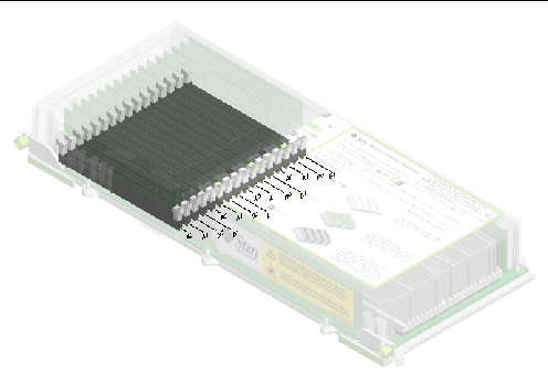
You must physically remove a CPU/Memory board from the system before you can install or remove DIMMs. The DIMMs must be added four-at-a-time within the same DIMM group, and each group used must have four identical DIMMs installed--that is, all four DIMMs in the group must be from the same manufacturing vendor and must have the same capacity (for example, four 512-Mbyte DIMMs or four 1-Gbyte DIMMs).

|
Caution - DIMMs are made of electronic components that are extremely sensitive to static electricity. Static from your clothes or work environment can destroy the modules. Do not remove a DIMM from its antistatic packaging until you are ready to install it on the system board. Handle the modules only by their edges. Do not touch the components or any metal parts. Always wear an antistatic grounding strap when you handle the modules. For more information, refer to How to Avoid Electrostatic Discharge. |
You can maximize the system's memory bandwidth by taking advantage of its memory interleaving capabilities. Sun Fire V490 systems support two-way, four-way, and eight-way memory interleaving. In most cases, higher interleaving factors result in greater system performance. However, actual performance results may vary depending on the system application.
The system's interleaving capabilities are summarized as follows:
Each Sun Fire V490 CPU/Memory board contains two independent memory subsystems (one per UltraSPARC IV processor). Memory controller logic incorporated into the UltraSPARC IV processor allows each processor to control its own memory subsystem. One processor controls DIMM groups A0 and A1, while the other processor controls DIMM groups B0 and B1.
The Sun Fire V490 system uses a shared memory architecture. During normal system operations, the total system memory is shared by all processors in the system. However, in the event of a processor failure, the two DIMM groups associated with the failed processor become unavailable to the other processors in the system.
TABLE 3-1 shows the association between the processors and their corresponding DIMM groups.
For guidelines and complete instructions on how to install DIMMs in a CPU/Memory board, refer to the Sun Fire V490 Server Parts Installation and Removal Guide.
All system communication with storage peripherals and network interface devices is mediated by two Peripheral Component Interconnect (PCI) bridge chips, located on the system's centerplane. Each bridge chip manages communication between the system's main interconnect bus and two PCI buses, giving the system a total of four separate PCI buses. The four PCI buses support up to six PCI interface cards and four centerplane devices.
TABLE 3-2 describes the PCI bus characteristics and maps each bus to its associated bridge chip, integrated devices, and PCI card slots. All slots comply with PCI Local Bus Specification Revision 2.1.
|
Note - PCI cards in a Sun Fire V490 system are not hot-pluggable. |
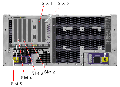
FIGURE 3-2 shows the PCI card slots on the PCI riser board.
The system controller (SC) card enables access, monitoring, and control of the
Sun Fire V490 server from a remote location. It is a fully independent processor card with its own resident firmware, power-on self-test (POST) diagnostics, and real-time operating system.

The SC card features serial and Ethernet interfaces that provide simultaneous access to the Sun Fire V490 server for multiple RSC software users. RSC software users are provided secure access to the system's Solaris and OpenBoot console functions and have full control over power-on self-test (POST) and OpenBoot Diagnostics.
The SC card runs independently of the host server, and operates off of 5V standby power from the system's power supplies. The card features on-board devices that interface with the system's environmental monitoring subsystem and can automatically alert administrators to system problems. Together these features enable the SC card and RSC software to serve as a "lights out" management tool that continues to function even when the server operating system goes offline or when the system is powered off.
The SC card plugs in to a dedicated slot on the system PCI riser board and provides the following ports (listed in order from top to bottom, as shown in FIGURE 3-4) through an opening in the system's back panel:
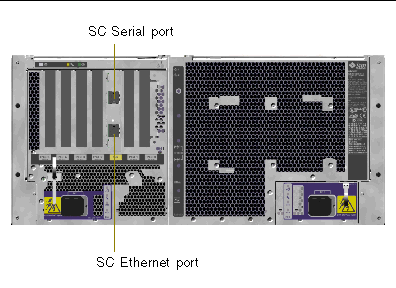
Both SC connection ports can be used simultaneously or individually disabled.
|
Note - You must install the Solaris OS and the Sun Remote System Control software prior to setting up an SC console. For more information, refer to How to Monitor the System Using the System Controller and RSC Software. |
Once you install the operating system and the RSC software, you can then configure the system to use the SC as the system console. For detailed instructions, refer to How to Redirect the System Console to the System Controller.
Three jumpers are located on the Sun Fire V490 system's PCI riser board. Note that jumpers are set at the factory to ensure best system performance. Be aware that moving any jumper shunt from its default location can render the system unstable or unusable.
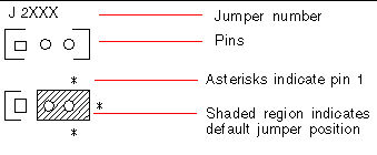
All jumpers are marked with identification numbers. For example, the jumpers on the system PCI riser board are marked J1102, J1103, and J1104. Jumper pins are located immediately adjacent to the identification number. The default jumper positions are indicated on the board by a white outline. Pin 1 is marked with asterisks (*), as shown in FIGURE 3-5.
On the PCI riser board are three jumpers, two of which affect transactions with the system Boot PROM and one of which is reserved for future use. FIGURE 3-6 illustrates the locations of these three jumpers.
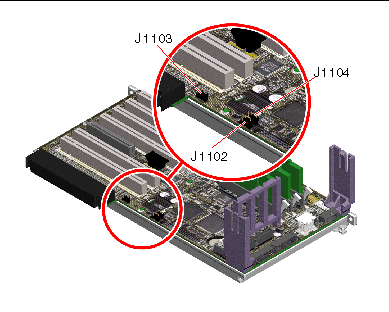
The functions of the PCI riser board jumpers are shown in TABLE 3-3.
|
|
Optional debug device populating connector in position J1101 |
||
|
|
|||
|
|
Each jumper on the PCI riser board has two options, as described in the following list.
A central power distribution board (PDB) delivers DC power to all internal system components. The system's two standard power supplies--called Power Supply 0 and Power Supply 1--plug in directly to connectors on this board, and all of the supplies installed share equally in satisfying the power demands of the system. AC power is brought into the PDB by way of two board-mounted IEC320 receptacles, each dedicated to one power supply.
The Sun Fire V490 system's N+1 redundant power supplies are modular units, designed for fast, easy installation or removal, even while the system is fully operational. Power supplies are installed in bays at the front of the system, as shown in the following figure.
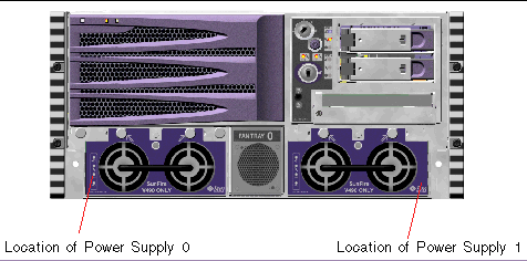
The power supplies operate over an AC input range of 200-240 VAC, 50-60 Hz, without user intervention. The power supplies are capable of providing up to 1448 watts of DC power. The basic system configuration comes with two power supplies installed, either of which is capable of providing sufficient power for a maximally configured system.
The power supplies provide 48-volt and 5-volt standby outputs to the system. The 48-volt output powers point-of-load DC/DC converters that provide 1.5V, 1.8V, 2.5V, 3.3V, 5V, and 12V to the system components. Output current is shared equally between both supplies via active current-sharing circuitry.
Power supplies in a redundant configuration feature a hot-swap capability. You can remove and replace a faulty power supply without shutting down the operating system or turning off the system power. For additional details, refer to About Hot-Pluggable and Hot-Swappable Components.
Each power supply has separate status LEDs to provide power and fault status information. For additional details, refer to How to Isolate Faults Using LEDs.

|
Caution - If any power supply fails, leave the supply in its bay until you are ready to install a replacement. |
For information about installing power supplies, refer to the Sun Fire V490 Server Parts Installation and Removal Guide, which is included on the Sun Fire V490 Documentation CD.
The basic system is equipped with five fans mounted on two fan trays, providing front-to-rear cooling: Fan Tray 0, which holds three fans that cool the CPUs, and Fan Tray 1, which holds two fans that cool the FC-AL drives and PCI cards. Fan Tray 0 is accessible from the front of the system, while Fan Tray 1 requires that you remove the system's PCI access panel to gain access to it. Power supplies are cooled separately, each with its own internal fans.

|
Caution - A complete set of two working fan trays mustbe present in the system at alltimes. After removing a fan tray, you mustinstall a replacement fan tray. Failure to install a replacement tray could lead to serious overheating of your system and result in severe damage to the system. For more information, refer to Environmental Monitoring and Control. |
The following figure shows both fan trays. The figure on the left shows Fan Tray 0, which cools the CPUs. The figure on the right shows Fan Tray 1, which cools the
FC-AL drives and PCI cards.
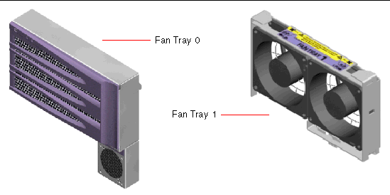
Status for each fan tray is indicated by separate LEDs on the system's front panel, which are activated by the environmental monitoring subsystem. The fans operate at full speed all the time--speed is not adjustable. Should a fan speed fall below a predetermined threshold, the environmental monitoring subsystem prints a warning and lights the appropriate Fault LED. For additional details, refer to How to Isolate Faults Using LEDs.
For each fan in the system, the environmental monitoring subsystem monitors or controls the following:
Fibre Channel (FC) is a high-performance serial interconnect standard designed for bidirectional, point-to-point communication among servers, storage systems, workstations, switches, and hubs.
Fibre Channel-Arbitrated Loop (FC-AL) is an important enhancement to the FC standard, developed specifically to meet the needs of storage system interconnects. Employing a simple loop topology, FC-AL can support both simple configurations and complex arrangements of hubs, switches, servers, and storage systems.
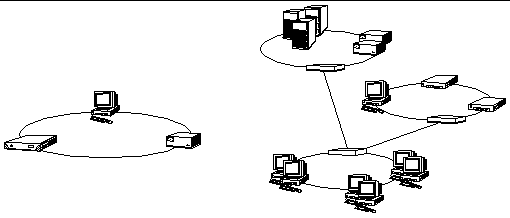
FC-AL devices employ a high-performance serial interface, which supports multiple standard protocols such as Small Computer Systems Interface (SCSI) and Asynchronous Transfer Mode (ATM). By supporting these standard protocols, FC-AL preserves any investment in legacy systems, firmware, applications, and software.
The unique features of FC-AL provide many advantages over other data transfer technologies. For additional information about FC-AL technology, visit the Fibre Channel Association Web site at http://www.fibrechannel.org.
The following table lists the features and advantages of FC-AL technology.
|
Supports 100-Mbyte per second data transfer rate (200 Mbytes per second with dual porting). |
High throughput meets the demands of current generation high-performance processors and disks. |
|
Capable of addressing up to 127 devices per loop (controlled by a single controller)[1]. |
High connectivity controlled by one device allows flexible and simpler configurations. |
|
Provides for reliability, availability, and serviceability (RAS) features such as hot-pluggable and dual-ported disks, redundant data paths, and multiple host connections. |
RAS features provide improved fault tolerance and data availability. |
|
Migration to FC-AL produces small or no impact on software and firmware. |
|
|
Implements a simple serial protocol over copper or fiber cable. |
Configurations that use serial connections are less complex because of the reduced number of cables per connection. |
All Sun Fire V490 servers include a single FC-AL backplane with connections for two internal hard disks, both of which are hot-pluggable.
The FC-AL backplane accepts two, low-profile (1.0-inch, 2.54-cm), dual-ported
FC-AL disk drives. Each disk drive is connected to the backplane via a standard 40-pin single connector attachment (SCA) interface. Incorporating all power and signal connections into a single, blind-mating connector, SCA technology makes it easy to add or remove disk drives from the system. Disks using SCA connectors provide higher availability and better serviceability than disks using other types of connectors.
The FC-AL backplane provides dual-loop access to both internal disk drives. Dual-loop configurations enable each disk drive to be accessed through two separate and distinct data paths. This capability provides:
|
Note - To take advantage of the dual-loop capability of the FC-AL backplane, an optional PCI FC-AL host adapter card must be installed to control the second loop (Loop B). For more information, refer to About the FC-AL Host Adapters. |
Port bypass controllers (PBCs) on the disk backplane ensure loop integrity. When a disk or external device is unplugged or fails, the PBCs automatically bypass the device, closing the loop to maintain data availability.
For information about installing or removing an FC-AL disk or disk backplane, refer to the Sun Fire V490 Server Parts Installation and Removal Guide, which is included on the Sun Fire V490 Documentation CD.
The Sun Fire V490 system back panel includes an FC-AL port with a high-speed serial data connector (HSSDC).
|
Note - At this time, no Sun storage products are supported utilizing the HSSDC connector. |
The Sun Fire V490 server uses an intelligent Fibre Channel processor as its on-board FC-AL controller. Integrated into the system centerplane, the processor resides on PCI Bus C and supports a 64-bit, 66-MHz PCI interface. The on-board FC-AL controller controls FC-AL operations on Loop A.
To take advantage of the dual-loop capability of the FC-AL backplane, an optional PCI FC-AL host adapter card and optional cable are required to control the second loop (Loop B). For this purpose, Sun offers the Sun StorEdge PCI Dual Fibre Channel Host Adapter card. Refer to the Sun Fire V490 Server Parts Installation and Removal Guide, which is included on the Sun Fire V490 Documentation CD, for installation instructions.
The Sun Fire V490 system includes two internal, low-profile (1.0-inch, 2.54-cm)
FC-AL disk drives, attached to a backplane. (The system also includes an external FC-AL port; refer to the section, About the HSSDC FC-AL Port.) Internal disks are available in different storage capacities. For the latest information about disk drive capacities, refer to the Sun Fire V490/V890 CPU/Memory Module Configuration Guide at:
http://www.sun.com/products-n-solutions/hardware/docs/Servers/
Sun Fire V490 disk drives are dual-ported for multipath access. When used in a dual-loop configuration--with the optional addition of a second FC-AL controller on a PCI adapter card--each drive can be accessed through two separate and distinct data paths.
Sun Fire V490 disk drives are hot-pluggable. You can add, remove, or replace disks while the system continues to operate. This capability significantly reduces system downtime associated with disk drive replacement. Disk drive hot-plug procedures involve software commands for preparing the system prior to removing a disk drive and for reconfiguring the operating system after installing a drive. For detailed instructions, refer to the Sun Fire V490 Server Parts Installation and Removal Guide, which is included on the Sun Fire V490 Documentation CD.
Three LEDs are associated with each drive, indicating the drive's operating status, hot-plug readiness, and any fault conditions associated with the drive. These status LEDs help you quickly to identify drives requiring service. Refer to TABLE 2-3 for a description of these LEDs.
The system provides a serial communication port through an RJ-45 connector located on the back panel. The port supports baud rates of 50, 75, 110, 200, 300, 600, 1200, 1800, 2400, 4800, 9600, 19200, 38400, 57600, 76800, 115200, 153600, 230400, 307200, and 460800.
The port is accessible by connecting an RJ-45 serial cable to the back panel serial port connector. For your convenience, a serial port adapter (part number 530-2889-03) is included in your Sun Fire V490 server ship kit. This adapter enables you to use a standard RJ-45 serial cable to connect directly from the serial connector on the back panel to a Sun workstation, or to any other terminal that is equipped with a DB-25 serial connector.
For the serial port location, refer to Locating Back Panel Features. Also refer to Appendix A.
The system's back panel provides two external Universal Serial Bus (USB) ports for connection to USB peripheral devices such as:
For USB port locations, refer to Locating Back Panel Features.
The USB ports are compliant with the Open Host Controller Interface (Open HCI) specification for USB Revision 1.0. Both ports support isochronous and asynchronous modes. The ports enable data transmission at speeds of 1.5 Mbps and 12 Mbps. Note that the USB data transmission speed is significantly faster than that of the standard serial ports, which operate at a maximum rate of 460.8 Kbaud.
The USB ports are accessible by connecting a USB cable to either back panel USB connector. The connectors at each end of a USB cable are different, so you cannot connect them incorrectly. One connector plugs in to the system or USB hub; the other plugs in to the peripheral device. Up to 126 USB devices can be connected to the bus simultaneously, through the use of USB hubs. The Universal Serial Bus provides power for smaller USB devices such as modems. Larger USB devices, such as scanners, require their own power source.
Both USB ports support hot-plugging. You can connect and disconnect the USB cable and peripheral devices while the system is running, without affecting system operations. However, you can only perform USB hot-plug operations while the operating system is running. USB hot-plug operations are not supported when the system ok prompt is displayed.
Copyright © 2004, Sun Microsystems, Inc. All Rights Reserved.