| C H A P T E R 3 |
|
Hardware Configuration |
This chapter provides hardware configuration information for the Sun Fire V890 server. The following topics are covered in this chapter:
|
Note - For configuration information about the internal mass storage subsystem, see Mass Storage Subsystem Configuration. For configuration information about network interfaces, see Configuring Network Interfaces. |
The system motherboard provides slots for up to four CPU/Memory boards. Each CPU/Memory board incorporates two UltraSPARC chip multithreading (CMP) processors, with 16 Mbytes of static random access memory (SRAM) Level 2 external cache memory per processor, and slots for 16 memory modules. The external cache memory cannot be upgraded.
|
Note - You must use CPU/Memory boards of the same speed within a Sun Fire V890 system. |
Chip multithreading technology allows two threads per UltraSPARC processor. With this dual-threaded architecture, each UltraSPARC processor consists of two virtual processors with shared memory. A dynamic arbitration scheme enables each thread to make optimal use of the available memory, resulting in higher performance.
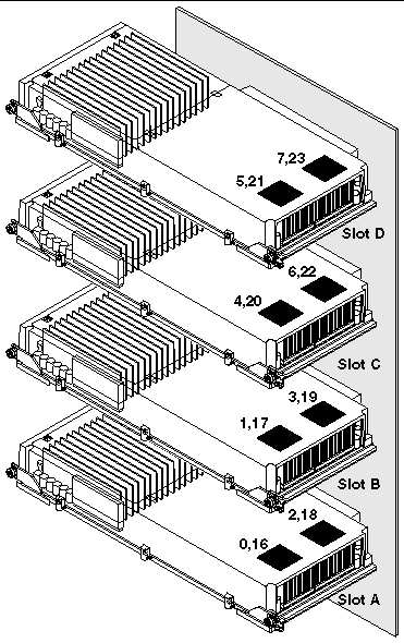
The following illustration shows the four CPU/Memory board slots on the system motherboard. The slots are labeled A through D from bottom to top. The virtual processors (CPUs) in the system have unique numbers, depending on the slot where each CPU/Memory board resides. For example, a CPU/Memory board installed in slot D always contains CPUs 5 and 21 and 7 and 23, even if there are no other CPU/Memory boards installed in the system.
The UltraSPARC processor is a high-performance, highly integrated, CMP processor that enables an increase in application throughput while maintaining binary compatibility. It implements a 64-bit SPARC International Version 9 Instruction Set Architecture (ISA).
The UltraSPARC processor improves throughput performance in commercial applications such as databases, web servers, and high-performance technical computing. It supports both 2D and 3D graphics, as well as image processing, video compression and decompression, and video effects through the sophisticated Visual Instruction Set (VIS) extension. VIS provides high levels of multimedia performance, including real-time video compression and decompression and two streams of MPEG-2 decompression at full broadcast quality with no additional hardware support.
The Sun Fire V890 server employs a shared-memory multiprocessor architecture with all processors sharing the same physical address space. The UltraSPARC processors, main memory, and I/O subsystem communicate via a high-speed system interconnect bus, operating at a clock rate of 150 MHz. In a system configured with multiple CPU/Memory boards, all main memory is accessible from any processor over the system bus. The main memory is shared logically by all processors and I/O devices in the system.
For information about memory modules and memory configuration guidelines, see About Memory Modules.

|
Caution - CPU/Memory boards must be installed only by a qualified service technician. After installing a CPU/Memory board, you must perform a reconfiguration boot in order for the environmental software to recognize the new device. See How to Initiate a Reconfiguration Boot. |
The Sun Fire V890 server uses 3.3-volt, high-capacity dual inline memory modules (DIMMs). The DIMMs are built with synchronous dynamic random access memory (SDRAM) chips that operate at a 75-MHz clock frequency. The system supports DIMMs of various capacities. For details, see the Sun Fire V490/V890 CPU/Memory Module Configuration Guide, available from:
http://www.sun.com/products-n-solutions/hardware/docs/Servers/
Each CPU/Memory board contains slots for 16 DIMMs. Total system memory available depends on the capacity of the DIMMs installed.
Within each CPU/Memory board, the 16 DIMM slots are organized into groups of four. The system reads from, or writes to, all four DIMMs in a group simultaneously. DIMMs, therefore, must be added in sets of four.
The figure below shows the DIMM slots and DIMM groups on a Sun Fire V890 CPU/Memory board. Every fourth slot belongs to the same DIMM group. The four groups are designated A0, A1, B0, and B1.
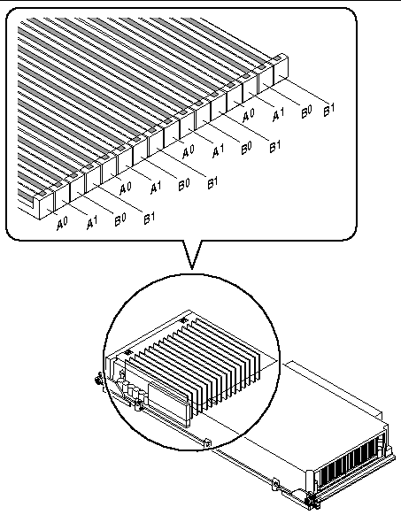
Qualified service technicians must physically remove a CPU/Memory board from the system before installing or removing DIMMs. The DIMMs must be added four at a time within the same DIMM group and be identical--that is, all DIMMs must be from the same manufacturing vendor and must have the same capacity (for example, four 512-Mbyte DIMMs, or four 1-Gbyte DIMMs).
You can maximize the system's memory bandwidth by taking advantage of its memory interleaving capabilities. Sun Fire V890 systems support two-way, four-way, and eight-way memory interleaving. In most cases, higher interleaving factors result in greater system performance. However, actual performance results may vary depending on the system application.
The system's interleaving capabilities are summarized as follows:
Each Sun Fire V890 CPU/Memory board contains two independent memory subsystems (one per UltraSPARC processor). Memory controller logic incorporated into the UltraSPARC processor enables each processor to control its own memory subsystem. One processor controls DIMM groups A0 and A1, while the other processor controls DIMM groups B0 and B1.
The Sun Fire V890 system uses a shared-memory architecture. During normal system operations, the total system memory is shared by all processors in the system. However, in the event of a processor failure, the two DIMM groups associated with the failed processor become unavailable to all other processors in the system.
The following table shows the association between the processors and their corresponding DIMM groups.
The following table summarizes the guidelines for installing DIMMs in a CPU/Memory board. DIMMs must be installed by a qualified service technician. Refer to the Sun Fire V890 Server Service Manual, which is included on the Sun Fire V890 Documentation CD for installation instructions.
All system communication with storage peripherals and network interface devices is mediated by two Peripheral Component Interconnect (PCI) bridge chips, located on the system's motherboard. Each bridge chip manages communication between the system's main interconnect bus and two PCI buses, giving the system a total of four separate PCI buses. The four PCI buses support up to nine PCI interface cards and four motherboard devices.
The following table describes the PCI bus characteristics and maps each bus to its associated bridge chip, motherboard devices, and PCI slots. All slots comply with PCI Local Bus Specification Revision 2.1.
|
System controller card, RIO ASIC (Ethernet, USB, and EBus interfaces) |
The system's PCI hot-plug feature allows a qualified service technician to remove and install PCI cards while the system is running. A qualified service technician can hot-plug any standard PCI card, provided that its Solaris device drivers support PCI hot-plug operations, and the system is running a Solaris Operating System that supports Sun Fire V890 PCI hot-plug operations. In addition, the PCI card must comply with the PCI Hot-Plug Specification Revision 1.1.
PCI hot-plug procedures may involve software commands for preparing the system prior to removing a card and for reconfiguring the operating system after installing a PCI card. For more information about PCI hot-plug procedures, see About Hot-Pluggable and Hot-Swappable Components.
Status LEDs provide power, fault, and hot-plug status indications for each PCI slot. A contact push button is also provided for each slot, which allows the service technician to initiate the hot-plug procedure at the server. For information about the status indicator LEDs, see About PCI Slot LEDs.
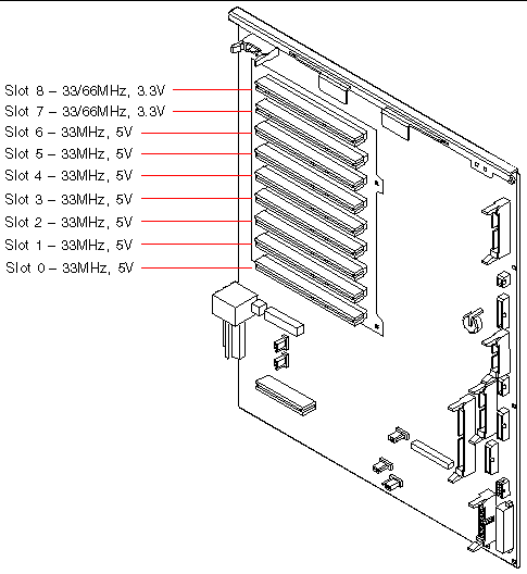
The following figure shows the PCI slots on the I/O board.
The system controller (SC) card, combined with the Remote System Control (RSC) software, enables access, monitoring, and control of the Sun Fire V890 server from a remote location. It is a fully independent processor card with its own resident firmware, power-on self-test (POST) diagnostics, and real-time operating system. The card features serial and Ethernet interfaces that provide simultaneous access to the Sun Fire V890 server for multiple RSC users. RSC users are provided secure access to the system's Solaris and OpenBoot console functions and have full control over POST and OpenBoot Diagnostics.
The system controller card runs independently of the host server, and operates on 5-volt standby power from the system's power supplies. The card features on-board devices that interface with the system's environmental monitoring subsystem and can automatically alert administrators to system problems. Together these features allow the system controller card and RSC software to serve as a "lights-out" management tool that continues to function even when the server operating system goes offline or the system is powered off.
The system controller card plugs in to a dedicated slot on the system I/O board and provides the following ports through an opening in the system rear panel:

The two system controller ports can be used simultaneously.
|
Note - You must install the Solaris Operating System and the Sun Remote System Control software prior to setting up an RSC console. For more information, see About Sun Remote System Control Software. |
Once you install the operating system and the RSC software, you can then configure the system to use RSC as the system console. For detailed instructions, see How to Redirect the System Console to RSC.
A qualified service technician can install the system controller card into a dedicated slot at the base of the system I/O board. Never move the system controller card to another system slot, as it is not a PCI-compatible card.
A central power distribution board delivers DC power to all internal system components. The system's power supplies plug in to connectors on this board, and all of the supplies installed share equally in satisfying the power demands of the system.
Sun Fire V890 power supplies are modular units, designed for fast, easy installation or removal, even while the system is fully operational. Power supplies are installed in bays at the rear of the system, as shown in the following figure.
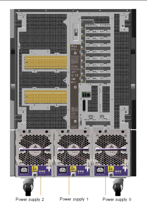
The system can accommodate a maximum of three power supplies, each with its own 10-amp AC power cord. Each power supply provides up to 1629 watts of DC power at 200-240 VAC line input. The basic system configuration comes with three power supplies installed. The third power supply provides N+1 power redundancy, allowing the system to continue operating should any one of the power supplies fail.
Each power supply provides a total of five DC output voltages (3.3V, 5.0V, 12V, 48V, and 5.0V standby). Output current is shared equally between each of the supplies via active current sharing circuitry.
Power supplies in a redundant configuration feature a hot-swap capability. You can remove and replace a faulty power supply without shutting down the operating system or turning off the system power. For additional details, see About Hot-Pluggable and Hot-Swappable Components.
Each power supply has three status LEDs to provide power and fault status information. For additional details, see About Power Supply LEDs.

|
Caution - If any power supply fails, leave the supply in its bay until you are ready to install a replacement. |
For information about installing power supplies, see the Sun Fire V890 Server Service Manual, which is included on the Sun Fire V890 Documentation CD.
The basic system is equipped with three fan trays: a CPU fan tray, an I/O fan tray, and a motherboard fan tray. The CPU and I/O fan trays contain two fans apiece, while the motherboard fan tray contains a single fan. All systems are equipped with this primary set of fan trays and redundant cooling from a secondary set of the same fan trays.
The motherboard fan tray is also known as the I/O bridge fan tray since its primary purpose is to cool the I/O bridge chips on the system motherboard.
The following table describes the system's fan trays.
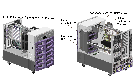
Only the primary fan trays are running during normal system operation. If a primary fan tray fails, the environmental monitoring subsystem detects the failure and automatically activates the secondary fan tray.
All fan trays feature a hot-swap capability. Qualified service technicians can remove and replace a faulty fan tray without shutting down the operating system or turning off the system power. For additional details, see About Hot-Pluggable and Hot-Swappable Components.
For each fan in the system, the environmental monitoring subsystem monitors or controls the following:
Only the primary CPU fans have variable speed control. The secondary CPU fans, the primary and secondary motherboard fans, and the primary and secondary I/O fans can only be turned fully on or fully off. Fan speed is controlled by the environmental monitoring subsystem in response to temperature conditions inside the system. For additional details, see Environmental Monitoring and Control.
Status indicator LEDs provide power, fault, and hot-swap indications for each fan tray. For information about the status indicator LEDs, see About Fan Tray LEDs.

|
Caution - A complete set of three working fan trays must be present in the system at all times. After removing a fan tray, if the system is left with fewer than three working fan trays, a qualified service technician must install a replacement fan tray immediately to avoid an automatic thermal shutdown. For more information, see Environmental Monitoring and Control. |
The Sun Fire V890 system provides front-panel access to three mounting bays. One bay houses an IDE DVD-ROM drive, which comes standard in all system configurations. The other two bays can house optional wide (68-pin) SCSI removable devices, which must be ordered separately. The tape drive option also requires a SCSI cable and a SCSI adapter card; both must be ordered separately. A qualified service technician can easily convert the two SCSI device bays into a single full-height bay by removing a metal shelf divider.
The SCSI bus that supports the removable media devices is Fast/Wide-capable (20 Mbytes per second) and can support single-ended, wide SCSI devices.
Target addresses (also know as SCSI IDs) for the SCSI bus are available in the ranges of 0 through 5 and 8 through 15.
The target address reserved for the optional tape drive is 5.
If no tape drive is installed, you can use this address for an external device. If you later install an internal tape drive, you must use 5 as its address and assign a different address to the external device.
The system provides two serial communication ports through a single, shared DB-25 connector located on the rear panel. The primary port is capable of both synchronous and asynchronous communication, while the secondary port is asynchronous only. In synchronous mode, the primary port operates at any rate from 50 Kbaud to 256 Kbaud when the clock is generated internally. When the clock is generated from an external source, the synchronous port operates at rates up to 384 Kbaud. In asynchronous mode, either port supports baud rates of 50, 75, 110, 200, 300, 600, 1200, 1800, 2400, 4800, 9600, 19200, 38400, 57600, 76800, 115200, 153600, 230400, 307200, and 460800.
The primary port is accessible by connecting a standard serial cable to the rear panel serial port connector. To access the secondary port, you must attach a serial port splitter cable (Sun part number X985A) to the rear panel serial port connector. The connector labeled "A" on the splitter cable provides the primary port; the connector labeled "B" provides the secondary port.
A qualified service technician can configure both serial ports to comply with the Electronics Industries Association EIA-423 or EIA-232D standards using jumpers located on the system's I/O board. The jumpers are factory-set for the EIA-423 standard, which is the default standard for North American users. Compliance with the EIA-232D standard is required for digital telecommunication in nations of the European Community. For more information about configuring the serial port jumpers, see This illustration depicts the location of the serial port jumpers on the I/O board..
See Reference for the Serial Port A and B Connectors for the connector diagram, rear panel icon, and pin assignments.
The system's rear panel provides two Universal Serial Bus (USB) ports for connection to USB peripheral devices such as:
For USB port locations, see Locating Rear Panel Features.
The USB ports are compliant with the Open Host Controller Interface (Open HCI) specification for USB Revision 1.0. Both ports support isochronous and asynchronous modes and enable data transmission at speeds of 1.5 Mbps and 12 Mbps. Note that the USB data transmission speed is significantly faster than that of the standard serial ports, which operate at a maximum rate of 460 Kbaud.
The USB ports are accessible by connecting a USB cable to either rear panel USB connector. The connectors at each end of a USB cable are different, so you cannot connect them incorrectly. One connector plugs in to the system or USB hub; the other plugs in to the peripheral device. Up to 126 USB devices can be connected to the bus simultaneously, through the use of USB hubs.
|
Note - The Universal Serial Bus provides power for smaller USB devices such as modems. Larger USB devices, such as scanners, require their own power source. |
Both USB ports support hot-plugging. You can connect and disconnect the USB cable and peripheral devices while the system is running, without affecting system operations.
|
Note - You can only perform USB hot-plug operations while the operating system is running. USB hot-plug operations are not supported when the system ok prompt is displayed. |
The hardware jumpers in the Sun Fire V890 server have the following functions:

|
Caution - All internal jumper modifications must be performed only by qualified service personnel. |

|
Caution - Do not change the configuration of J0501 and J0502 on the system controller card from the default settings; otherwise, the system controller card will not boot. |
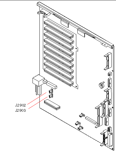
All jumpers are marked with identification numbers. For example, the serial port jumpers on the system I/O board are marked J2902 and J2903. Jumper pins are located immediately adjacent to the identification number. The default jumper positions are indicated with shaded regions. Pin 1 is marked with an asterisk (*) in any of the positions shown below.

The serial port jumpers (J2902 and J2903) on the system I/O board configure the system's two serial ports for either EIA-423 or EIA-232D signal levels. EIA-423 levels are the default standard for North American users. EIA-232D levels are required for digital telecommunication in nations of the European Community.
|
|
|||
|
|
The Sun Fire V890 system uses flash PROMs to enable the reprogramming of specific firmware code blocks held in nonvolatile system memory, and to enable remote reprogramming of that code by an authorized system administrator over a local area network. Firmware updates, when required, are available for download from the SunSolve Online web site at http://sunsolve.sun.com.
Instructions for performing a firmware update procedure are provided with the downloaded firmware image.
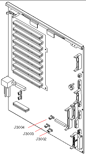
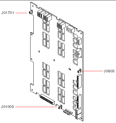
Several jumpers located on the system I/O board and FC-AL disk backplane affect flash PROM operation. The jumper locations and settings are provided in the sections that follow. For an explanation of how each jumper affects the flash PROM update procedure, see the instructions supplied with the firmware image.
The locations and functions of the flash PROM jumpers on the system I/O board are shown below.
|
|
|||
|
|
|||
|
|
The locations and functions of the flash PROM jumpers on the Fibre Channel-Arbitrated Loop (FC-AL) disk backplane are shown below.
|
|
|||
|
|
|||
|
|
Copyright © 2005, Sun Microsystems, Inc. All Rights Reserved.