| Sun Fire V890 Server Service Manual
|
   
|
This appendix gives you reference information about the system's rear panel ports and pin assignments. Topics covered in this appendix include:
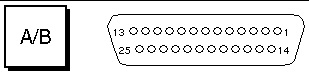
Reference for the Serial Port A and B Connectors
The serial port conforms to EIA-423 and EIA-232D specifications.
Serial Port Connector Diagram
Serial Port Signals
Signal descriptions ending in "A" indicate that the signal is associated with the port provided by a standard DB-25 serial cable or the connector labeled "A" on the optional DB-25 splitter cable. Signal descriptions ending in "B" indicate that the signal is associated with the port provided by the connector labeled "B" on the optional DB-25 splitter cable.
|
Pin
|
Signal Description
|
Pin
|
Signal Description
|
|
1
|
No Connection
|
14
|
Transmit Data B
|
|
2
|
Transmit Data A
|
15
|
Transmit Clock A (External)
|
|
3
|
Receive Data A
|
16
|
Receive Data B
|
|
4
|
Ready To Send A
|
17
|
Receive Clock A
|
|
5
|
Clear To Send A
|
18
|
Receive Clock B
|
|
6
|
Synchronous A
|
19
|
Ready To Send B
|
|
7
|
Signal Ground A
|
20
|
Data Terminal Ready A
|
|
8
|
Data Carrier Detect A
|
21
|
No Connection
|
|
9
|
No Connection
|
22
|
No Connection
|
|
10
|
No Connection
|
23
|
No Connection
|
|
11
|
Data Terminal Ready B
|
24
|
Transmit Clock A (Internal)
|
|
12
|
Data Carrier Detect B
|
25
|
Transmit Clock B
|
|
13
|
Clear To Send B
|
|
|
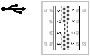
Reference for the USB Connectors
Two Universal Serial Bus (USB) connectors are located on the system I/O board and can be accessed from the rear panel.
USB Connector Diagram
USB Connector Signals
|
Pin
|
Signal Description
|
Pin
|
Signal Description
|
|
A1
|
+5 VDC
|
B1
|
+5 VDC
|
|
A2
|
Port Data_N
|
B2
|
Port Data_N
|
|
A3
|
Port Data_P
|
B3
|
Port Data_P
|
|
A4
|
Ground
|
B4
|
Ground
|
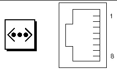
Reference for the Twisted-Pair Ethernet Connector
The twisted-pair Ethernet (TPE) connector is an RJ-45 connector located on the system I/O board and can be accessed from the rear panel.
TPE Connector Diagram
TPE Connector Signals
|
Pin
|
Signal Description
|
Pin
|
Signal Description
|
|
1
|
Transmit Data +
|
5
|
Common Mode Termination
|
|
2
|
Transmit Data -
|
6
|
Receive Data -
|
|
3
|
Receive Data +
|
7
|
Common Mode Termination
|
|
4
|
Common Mode Termination
|
8
|
Common Mode Termination
|
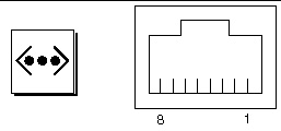
Reference for the System Controller Ethernet Connector
The system controller Ethernet connector is an RJ-45 connector located on the system controller board and can be accessed from the rear panel.
System Controller Ethernet Connector Diagram
System Controller Ethernet Connector Signals
|
Pin
|
Signal Description
|
Pin
|
Signal Description
|
|
1
|
Transmit Data +
|
5
|
Common Mode Termination
|
|
2
|
Transmit Data -
|
6
|
Receive Data -
|
|
3
|
Receive Data +
|
7
|
Common Mode Termination
|
|
4
|
Common Mode Termination
|
8
|
Common Mode Termination
|
Reference for the System Controller Serial Connector
The system controller serial connector is an RJ-45 connector located on the system controller card and can be accessed from the rear panel.
System Controller Serial Connector Diagram
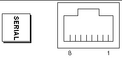
System Controller Serial Connector Signals
|
Pin
|
Signal Description
|
Pin
|
Signal Description
|
|
1
|
Ready To Send
|
5
|
Ground
|
|
2
|
Data Terminal Ready
|
6
|
Receive Data
|
|
3
|
Transmit Data
|
7
|
No Connection
|
|
4
|
Ground
|
8
|
Clear To Send
|
| Sun Fire V890 Server Service Manual
|
817-3957-12
|
|
Copyright © 2005, Sun Microsystems, Inc. All Rights Reserved.