| Sun Fire V890 Server Service Manual |
| Sun Fire V890 Server Service Manual |
| A P P E N D I X C |
|
Split Backplane Configurations |
|
Note - The procedures described in this appendix should be performed only by qualified service personnel. |
Two split backplane configurations are available for Sun Fire V890 servers that are equipped with both a base backplane and an expansion backplane:
The new configurations provide customers with enhanced hardware redundancy and data availability. See About the Split Backplane Configurations for a description of the new configurations.
This appendix includes the following sections, which provide the setup procedures for the new configurations as well as useful reference information:
The procedures in this appendix enable you to set up the new split backplane configurations for Sun Fire V890 servers that are equipped with both a base backplane and an expansion backplane. Before you perform the procedures:
Following are brief descriptions of the new configurations:
Before the Solaris Operating System can recognize the split backplane configurations, the following patches must be installed to upgrade the Sun Fire V890 server Fibre Channel backplane firmware:
The minimum OpenBoot firmware level is version 4.7.5. The recommended OpenBoot firmware level is version 4.10.8 (patch ID 112186-10) or later.
These patches are available on the SunSolve Online web site at http://sunsolve.sun.com.
To set up the split backplane configurations, you need PCI Dual FC Network Adapters and Fibre Channel cables in the quantities shown in the following table.
Before you begin to set up the split backplane single-loop configuration, verify that the Fibre Channel backplane firmware has been upgraded with the appropriate software patch cited in Firmware Patches Required. If the firmware is not upgraded, install the appropriate patch as instructed in the README document for the patch. Both the patch and the README document are available on the SunSolve Online web site at http://sunsolve.sun.com.
The following procedure is based on the assumption that the expansion backplane is already installed. If you need to install the expansion backplane, see How to Install the Expansion FC-AL Backplane for instructions.
To set up the split backplane single-loop configuration, complete the following steps:
1. Set the OpenBoot configuration variable auto-boot? to false.
3. Remove the primary and secondary I/O fan tray assemblies.
See How to Remove an I/O Fan Tray for instructions.
4. Disconnect the following cables (if installed) from the expansion backplane and the base backplane:
For cable connector locations, see Reference for Cable Routing and Connector Locations.
a. Base/expansion cable from both base and expansion backplane connectors J0801.
b. FC-AL data cable from base backplane connectors J01103 and J01102, and from expansion backplane connectors J01101 and J01100.
c. FC-AL data cable from expansion backplane connectors J0201 and J0200, and from base backplane connectors J0501 and J0500.
5. Choose a slot for the PCI Dual FC Network Adapter.
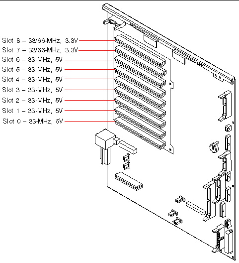
For higher throughput, select one of the 66-MHz slots (PCI slot 7 or 8). See Reference for PCI Slot Locations.
6. Install the PCI Dual FC Network Adapter.
See How to Install a PCI Card for PCI card installation instructions.
The PCI Dual FC Network Adapter contains two external optical transceiver connectors, located on the spine of the adapter. Pull the dust cover from each external connector before you install the adapter.
After you install the network adapter, replace the dust cover on the Port 1 connector. In this configuration, Port 1 of the network adapter cannot be used to connect to external devices. Use only Port 2 to connect to external devices.
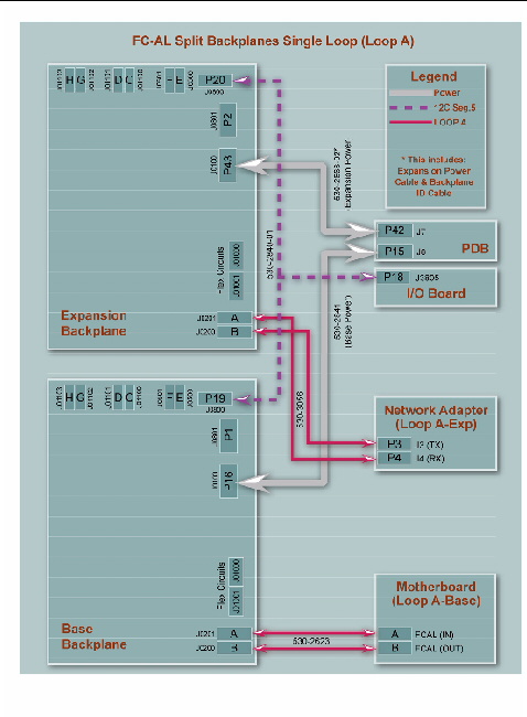
7. Connect the new FC-AL data cable (P3 and P4) to connectors J3 (P3) and J4 (P4) on the PCI Dual FC Network Adapter and to expansion backplane connectors (C) J0200 and (D) J0201.
See Reference for Cable Routing and Connector Locations for a quick reference for cable connections
8. Install the primary and secondary I/O fan trays. (See How to Install an I/O Fan Tray for instructions.) Check that the FC-AL data cable does not interfere with the fans. If necessary, use tie-wraps to attach the cable to the internal wall near the backplanes.


|
Caution - Before you power on the system, be sure that the front and side doors and all plastic outer panels are properly installed. |

9. Power on the system and access the ok prompt.
See How to Initiate a Reconfiguration Boot.
10. Verify that all disks and network adapters are recognized by the OpenBoot PROM. At the ok prompt, type the probe-scsi-all command.
11. Perform a reconfiguration boot of the Solaris software. At the ok prompt, type the boot -r command.
12. Verify that the Solaris software recognizes both the base and expansion backplanes. At the Solaris prompt, type the luxadm probe command.
# luxadm probe Found Enclosure(s): SUNWGS INT FCBPL Name:FCloop Node WWN:508002000017c4d8 Logical Path:/dev/es/ses0 SUNWGS INT FCBPL Name:FCloop Node WWN:50800200001cb798 Logical Path:/dev/es/ses2 |
The luxadm probe command displays the enclosure name, World Wide Number, and logical path name for each FC-AL backplane. Notice that the display shows the same enclosure name (FCloop in the example) for both backplanes. Also note the logical path name of each device. You need this information to perform Step 13.
13. Change the enclosure name of one of the FC-AL backplanes. Type the
luxadm enclosure_name command.
Each backplane must have a unique enclosure name. Use the luxadm enclosure_name command to assign a unique name by changing one of the enclosure names as shown in the following example.
To change the enclosure name, assign the new name (FCloop2 in the example) and enter the path name (/dev/es/ses2 in the example) of the appropriate backplane. You obtained the path name from the luxadm probe command output shown in Step 12.
|
Note - There is no output from the luxadm enclosure_name command. |
14. Verify that the Solaris software recognizes the correct enclosure name for each backplane. Type the luxadm probe command.
Notice that the output example now shows a unique name (FCloop and FCloop2 in the example) for each backplane.
# luxadm probe Found Enclosure(s): SUNWGS INT FCBPL Name:FCloop Node WWN:508002000017c4d8 Logical Path:/dev/es/ses0 SUNWGS INT FCBPL Name:FCloop2 Node WWN:50800200001cb798 Logical Path:/dev/es/ses2 |
15. Verify that the Solaris software recognizes all disks attached to each backplane. Type the luxadm display command and specify the enclosure name for each backplane.
In the following example, the base backplane (FCloop in the example) has six attached disks in slots 0 through 5.
The following example shows the luxadm display output for the expansion backplane (FCloop2 in the example).
Before you begin to set up the split backplane dual-loop configuration, verify that the Fibre Channel backplane firmware has been upgraded with the appropriate software patch cited in Firmware Patches Required. If the firmware is not upgraded, install the appropriate patch as instructed in the README document for the patch. Both the patch and the README document are available on the SunSolve Online web site at http://sunsolve.sun.com.
The following procedure is based on the assumption that the expansion backplane is already installed. If you need to install the expansion backplane, see How to Install the Expansion FC-AL Backplane for instructions.
To set up the split backplane dual-loop configuration, complete the following steps:
1. Set the OpenBoot configuration variable auto-boot? to false.
3. Remove the primary and secondary I/O fan tray assemblies.
See How to Remove an I/O Fan Tray for instructions.
4. Disconnect the following cables (if installed) from the expansion backplane and the base backplane:
For cable connector locations, see Reference for Cable Routing and Connector Locations.
a. Base/expansion cable from base and expansion backplane connector J0801.
b. FC-AL data cable (Loop B) from base backplane connectors J01103 and J01102 and from expansion backplane connectors J01101 and J01100.
c. FC-AL data cable (Loop A) from expansion backplane connectors J0201 and J0200 and from base backplane connectors J0501 and J0500.
5. Choose the slots for the PCI Dual FC Network Adapters.
For easy cable routing, plan to install two of the PCI Dual FC Network Adapters in any two of PCI slots 0 through 6 and the other network adapter in PCI slot 7 or 8. Installing the network adapters in these slots enables you to route all three cables along the floor of the I/O compartment. See Reference for PCI Slot Locations.
6. Install the three PCI Dual FC Network Adapters.
See How to Install a PCI Card for instructions.
Each PCI Dual FC Network Adapter contains two external optical transceiver connectors, located on the spine of the adapter. Pull the dust cover from each external connector before you install the adapters.
After you install the network adapters, replace the dust covers on the Port 1 connectors. In this configuration, Port 1 of the network adapters cannot be used to connect to external devices. Use only Port 2 to connect to external devices.
7. Connect the three new FC-AL data cables as follows:
See Reference for Cable Routing and Connector Locations for a quick reference for cable connections.
a. For one of the PCI Dual FC Network Adapters in slots 0 through 6, connect a new FC-AL data cable (P3 and P4) from network adapter connectors J3 (P3) and J4 (P4) to expansion backplane connectors (C) J0200 and (D) J0201.
b. For the other PCI Dual FC Network Adapter in slots 0 through 6, connect a new FC-AL data cable (P3 and P4) from network adapter connectors J3 (P3) and J4 (P4) to expansion backplane connectors (C) J01100 and (D) J01101.
c. For the PCI Dual FC Network Adapter in slot 7 or 8, connect a new FC-AL data cable (P3 and P4) from network adapter connectors J3 (P3) and J4 (P4) to base backplane connectors (C) J01100 and (D) J01101.
|
Note - If you install Loop B, you must also install Loop A or the backplanes will not initialize. |
8. Install the primary and secondary I/O fan trays. (See How to Install an I/O Fan Tray for instructions.) Check that the FC-AL cables do not interfere with the fan. If necessary, use tie-wraps to attach the cables to the internal wall near the FC-AL backplanes.

|
Caution - Before you power on the system, be sure that the front and side doors and all plastic outer panels are properly installed. |
9. Power on the system and access the ok prompt.
See How to Initiate a Reconfiguration Boot.
10. Verify that all disks and network adapters are recognized by the OpenBoot PROM. At the ok prompt, type the probe-scsi-all command.
11. Perform a reconfiguration boot of the Solaris software. At the ok prompt, type the boot -r command.
12. Verify that the Solaris software recognizes both the base and expansion backplanes. At the Solaris prompt, type the luxadm probe command.
The luxadm probe command displays the enclosure name, World Wide Number, and logical path name for each FC-AL backplane. Notice that the display shows the same enclosure name (FCloop in the example) for both backplanes. Also note the logical path name of each device. You need this information to perform Step 13.
13. Change the enclosure name of one of the FC-AL backplanes. Type the
luxadm enclosure_name command.
Each backplane must have a unique enclosure name. Use the luxadm enclosure_name command to assign a unique name by changing one of the enclosure names as shown in the following example.
To change the enclosure name, assign the new name (FCloop2 in the example) and enter the path name (/dev/es/ses2 in the example) of the appropriate backplane. You obtained the path name from the output from the luxadm probe command shown in Step 12. You can enter either of the path names (/dev/es/ses2 or /dev/es/ses3) shown in Step 12.
|
Note - There is no output from the luxadm enclosure_name command. |
14. Verify that the Solaris software recognizes the correct enclosure name for each backplane. Type the luxadm probe command.
Notice that the output example now shows a unique name (FCloop and FCloop2 in the example) for each backplane.
15. Verify that the Solaris software recognizes all disks attached to each backplane. Type the luxadm display command and specify the enclosure name for each backplane.
In the following example, the base backplane (FCloop in the example) has six attached disks in slots 0 through 5.
The following example shows the luxadm display output for the expansion backplane (FCloop2 in the example).
Cable connection information for the split backplane single-loop and dual-loop configurations is shown in the following table.
|
Connections for the Two PCI FC Network Adapters Installed in Slots 0 through 6 |
||
|
Connections for the PCI FC Network Adapter Installed in Slot 7 or 8 |
||
The locations of the base and expansion backplane connectors are shown in the following figure.
The locations of the connectors on the PCI Dual FC Network Adapter are shown in the following figure.
The locations and characteristics of the PCI slots are shown in the following figure.
| Sun Fire V890 Server Service Manual | 817-3957-12 |
Copyright © 2005, Sun Microsystems, Inc. All Rights Reserved.