| Sun Fire V890 Server Service Manual |
| Sun Fire V890 Server Service Manual |
| C H A P T E R 6 |
|
Removing and Installing Backplanes and Cables |
This chapter describes how to remove and install backplanes and cables in the system. For a list of part numbers for field-replaceable units (FRUs) and optional equipment, see Illustrated Parts Breakdown.
The following tasks are covered in this chapter:
The following information is also included:
1. Disconnect the base/expansion cable (P43 and P2) from the expansion backplane at connectors J0100 and J0801.
For cable connector locations, see Cable Connector Locations.
2. Disconnect the two disk status flex circuit cables from the expansion backplane at connectors J01000 and J01001.
3. Disconnect the I2C cable (P20) from the expansion backplane at connector J0800.
4. Disconnect the FC-AL data cables (A and B) from the expansion backplane at connectors A(J0201) and B(J0200).
5. Disconnect the FC-AL data cables (D and C) from the expansion backplane at connectors D(J01101) and C(J01100).
6. Remove the three Phillips screws and nylon washers securing the expansion backplane to the disk cage.
Save the screws and washers to reinstall the replacement backplane.
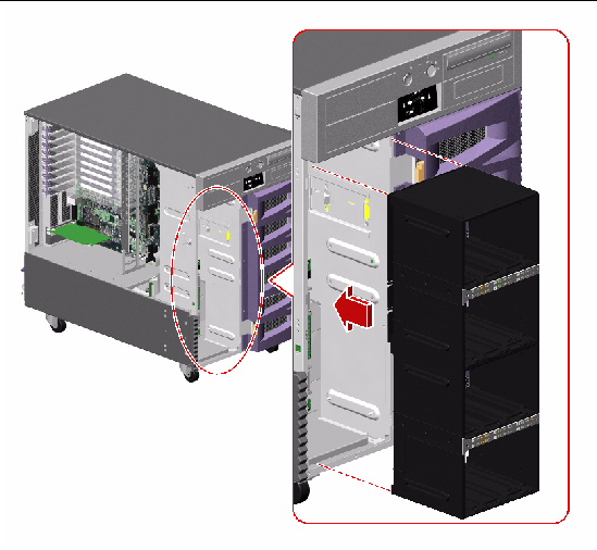
7. Remove the backplane from the system.
8. Place the expansion backplane on an antistatic mat.
9. If you are not immediately replacing the expansion backplane, install an FC-AL backplane filler panel, if you have one, on the disk cage.
a. Align the filler panel screw holes with the holes on the disk cage.
b. Fasten the three Phillips screws that secure the filler panel to the backplane.
10. If you are not immediately replacing the expansion FC-AL backplane, disconnect the base/expansion cable (P42) from connector P42/J7(DISKS) on the power distribution board and from connector J0801 on the base FC-AL backplane.
11. If you are not immediately replacing the expansion FC-AL backplane, disconnect the FC-AL data cable (F and E) from connectors F(J0501) and E(J0500) on the base FC-AL backplane.
To replace the expansion FC-AL backplane, complete this task:
To reassemble the system, complete this task:
If you are not replacing this part right away, you need to perform a reconfiguration boot in order for the operating system to recognize the configuration change. See:
1. If an FC-AL backplane filler panel is installed, remove the three Phillips screws securing the filler panel to the backplane and remove the filler panel from the system.
2. Position the expansion backplane in the system against the disk cage.
Align the three screw holes on the backplane with the screw holes on the disk cage.
3. Fasten the three screws and nylon washers that secure the backplane to the disk cage.
If you are installing the expansion backplane for the first time, the nylon washers are included with the backplane kit.
4. Connect the expansion FC-AL backplane cables to the backplane.
If you are installing an expansion backplane in the system for the first time, install the following cables:
a. FC-AL data cable (A and B) to connectors A(J0201) and B(J0200) on the expansion backplane and to connectors F(J0501) and E(J0500) on the base FC-AL backplane
b. Base/expansion cable (P42) to the power distribution board at connector P42/J7(DISKS)
c. Base/expansion cable (P1 - Base) to connector J0801 on the base backplane
d. Base/expansion cable (P2 and P43) to connector J0801 and J0100 on the expansion backplane
e. I2C cable (P20) to connector J0800 on the expansion backplane
The expansion backplane I2C cable is part of a cable assembly that includes the base backplane I2C cable that is already connected to the base backplane. The expansion backplane end of the cable is ganged with a group of cables running through the cable guides on the chassis centerplane and must be freed from the uppermost cable guide so that it can reach the expansion backplane.
If you are replacing the expansion FC-AL backplane, connect the following cables:
a. FC-AL data cable (F and E) from connectors F(J0501) and E(J0500) on the base backplane to connectors A(J0201) and B(J0200) on the expansion backplane
b. Base/expansion cable (P2 and P43) to connectors J0801 and J0100 on the expansion backplane
c. I2C cable (P20) to connector J0800 on the expansion backplane
5. Connect the Loop B FC-AL data cable (H and G) to connectors H(J01103) and G(J01102) on the base backplane and to connectors C(J01100) and D(J01101) on the expansion backplane.
6. Connect the two disk status flex circuit cables to the expansion backplane at connectors J01000 and J01001.
7. To reassemble the system, complete these tasks:
a. How to Install a Disk Drive
b. How to Install an I/O Fan Tray
8. After installing an expansion backplane, power on the system and bring up the system up to the ok prompt.
9. Allow the system to remain at the ok prompt for at least 10 minutes to ensure that the two backplanes are loaded with the same version of firmware.
The system automatically synchronizes the firmware versions between the two backplanes.
10. After the required waiting period, boot the system to single-user mode.
11. To verify that the firmware synchronization process has completed successfully, type the following luxadm subcommand:
where enclosure-name is the enclosure name assigned to the Sun Fire V890 internal storage array--by default, FCloop. If you need to verify the enclosure name first, use the luxadm probe subcommand.
The output of the display subcommand shows the status of each SSC100 processor in the system. The following is an excerpt of sample output for a dual-backplane system.
SSC100's - 0=Base Bkpln, 1=Base LoopB, 2=Exp Bkpln, 3=Exp LoopB SSC100 #0: O.K. (9228/ 3A20) SSC100 #1: O.K. (9228/ 3A20) SSC100 #2: O.K. (9228/ 3A20) SSC100 #3: O.K. (9228/ 3A20) |
Verify that each SSC100 processor displays an O.K. status and that each displays the same firmware version in parentheses. If so, the firmware synchronization process has completed successfully. Otherwise, wait another two minutes or so and repeat this process.
|
Note - For more information about the luxadm utility, refer to Platform Notes: Using the luxadm Software, which is included on the Sun Fire V890 Documentation CD. |
12. Once the firmware synchronization process is complete, you can restore the system to multiuser mode.
If you installed this part as a new option, you need to perform a reconfiguration boot in order for the operating system to recognize the new device. See:
1. If the expansion FC-AL backplane is installed, disconnect the following cables:
For cable connector locations, see Cable Connector Locations.
a. FC-AL data cable (H and G) from the base backplane at connectors H(J01103) and G(J01102)
b. FC-AL data cable (F and E) from the base backplane at connectors F(J01103) and E(J01102)
2. Disconnect the disk status flex circuit cables from the base backplane at connectors J01001 and J01000.
3. Remove the three Phillips screws and nylon washers securing the base backplane to the disk cage.
4. Remove the backplane from the system.
5. Place the backplane on an antistatic mat.
To replace the base FC-AL backplane, complete this task:
1. Position the base FC-AL backplane against the disk cage.
Align the three screw holes on the backplane with the screw holes on the disk cage.
2. Fasten the three screws and nylon washers that secure the backplane to the disk cage.
3. Connect the disk status flex circuit cables to the base backplane at connectors J01001 and J01000.
4. If the expansion FC-AL backplane is installed, connect the following cables:
For cable connector locations, see Cable Connector Locations.
a. FC-AL data cable (C and D) from connectors C(J01100) and D(J01101) on the expansion backplane to the base backplane at connectors H(J01103) and G(J01102)
a. FC-AL data cable (A and B) from connectors A(J0201) and B(J0200) on the expansion backplane to the base backplane at connectors F(J0501) and E(J0500)
5. To reassemble the system, complete these tasks:
a. How to Install the FC-AL Disk Cage
b. How to Install the CPU Fan Status Assembly
c. How to Install a CPU Fan Tray
d. How to Install an I/O Fan Tray
e. How to Install a Disk Drive
6. After installing an expansion backplane, power on the system and bring up the system to the ok prompt.
7. Allow the system to remain at the ok prompt for at least 10 minutes to ensure that the two backplanes are loaded with the same version of firmware.
The system automatically synchronizes the firmware versions between the two backplanes.
8. After the required waiting period, boot the system to single-user mode.
9. To verify that the firmware synchronization process has completed successfully, type the following luxadm subcommand:
where enclosure_name is the enclosure name assigned to the Sun Fire V890 internal storage array--by default, FCloop. If you need to verify the enclosure name first, use the luxadm probe subcommand.
The output of the display subcommand shows the status of each SSC100 processor in the system. The following is an excerpt of sample output for a dual-backplane system.
SSC100's - 0=Base Bkpln, 1=Base LoopB, 2=Exp Bkpln, 3=Exp LoopB SSC100 #0: O.K.(9226/ 3A20) SSC100 #1: O.K.(9226/ 3A20) SSC100 #2: O.K.(9226/ 3A20) SSC100 #3: O.K.(9226/ 3A20) |
Verify that each SSC100 processor displays an O.K. status and that each displays the same firmware version in parentheses. If so, the firmware synchronization process has completed successfully. Otherwise, wait another two minutes or so and repeat this process.
|
Note - For more information about the luxadm utility, refer to Platform Notes: Using luxadm Software, which is included on the Sun Fire V890 Documentation CD. |
10. Once the firmware synchronization process is complete, you can restore the system to multiuser mode.
If you installed this part as a new option, you need to perform a reconfiguration boot in order for the operating system to recognize the new device. See:
1. Remove the lower I/O fan tray bracket.
a. Disconnect the fan status cable (P27) from the back of the I/O fan flex circuit.
b. Remove the two Phillips screws securing the lower I/O fan tray bracket to the centerplane.
c. Rotate the lower I/O fan tray bracket out from the system.
d. Place the bracket on an antistatic mat.
2. Disconnect the following cables from each backplane installed:
For cable connector locations, see Cable Connector Locations.
a. Base/expansion cable and/or base backplane power cable from the backplane at connectors J0100 and J0801
b. I2C cable (P19) from the backplane at connector J0800
c. If a Sun StorEdge PCI Dual Fibre Channel Host Adapter card is connected to the base backplane, the FC-AL data cables from the base backplane at connectors C(J01100) and D(J01101)
3. Remove the I/O side fender from the system.
a. Remove the Phillips screw from the top of the fender.
b. Holding the front of the fender, rotate it out and away from the chassis.
The fender is held in place by two tabs on the back of the fender that fit into the lower chassis.
4. Remove the six CPU-side screws securing the disk cage to the system.
b. Remove the five screws securing the CPU fan tray guide to the chassis.
c. Remove the six CPU-side screws securing the mid-upper section of the disk cage to the chassis.
d. Loosen the two captive screws securing the lower section of the disk cage to the chassis.
The captive screws are accessed from two cutouts in the chassis, under the mounting point for the CPU fan tray guide.
5. Remove the eight I/O side screws securing the disk cage to the system.
6. Carefully pull the disk cage forward about 2 inches (5 cm), enough to give you clear access to the remaining cables on the base backplane.
7. Disconnect the base backplane FC-AL data cable (A and B) from the base backplane at connectors A(J0201) and B(J0200).
8. Slide the disk cage out fully from the system.
9. Place the disk cage on an antistatic mat.
To replace the disk cage, complete this task:
1. Carefully align the FC-AL disk cage with the disk cage bay.
2. Slide the disk cage into the system until it is about 2 inches (5 cm) from its final position in the disk cage bay.
3. Connect the base backplane FC-AL data cable (A and B) from the motherboard to the base backplane at connectors A(J0201) and B(J0200).
4. Slide the disk cage fully into the system.
5. On the I/O side of the system, loosely fasten the eight Phillips screws that secure the disk cage to the chassis.
Do not fully tighten the screws.
6. On the CPU side of the system, loosely fasten the six Phillips screws that secure the disk cage to the chassis.
Do not fully tighten the screws.
7. On the I/O side of the system, fully tighten the eight Phillips screws that secure the disk cage to the chassis.
8. On the CPU side of the system, fully tighten the six Phillips screws that secure the disk cage to the chassis.
9. Tighten the two captive screws that secure the lower section of the disk cage to the chassis.
The captive screws are accessed from two cutouts in the chassis, under the mounting point for the CPU fan tray guide.
10. Connect the following cables to the base backplane:
For cable connector locations, see Cable Connector Locations.
a. Base backplane power cable (P16) to the base backplane at connector J0100
The cable is connected to the power distribution board at connector P15/J8.
b. I2C cable (P19) to the base backplane at connector J0800
c. If a Sun StorEdge PCI Dual Fibre Channel Host Adapter card is installed to control Loop B of the FC-AL disk backplane, the card's FC-AL data cable to the base backplane at connectors C(J01100) and D(J01101)
11. If the expansion FC-AL disk backplane is installed, connect the following cables:
a. Base/expansion cable (P2 and P43) to the expansion backplane at connectors J0801 and J0100
b. Base/expansion cable (P1) to the base backplane at connector J0801
c. I2C cable (P20) to the expansion backplane at connector J0800
12. Replace the lower I/O fan tray bracket.
a. Connect the fan status cable (P27) to the connector on the back of the I/O fan status flex circuit.
b. Place the lower I/O fan bracket into the system against the centerplane.
Ensure that the ribbon cables behind the lower I/O fan bracket remain flat against the centerplane.
c. Fasten the two Phillips screws that secure the lower I/O fan tray bracket to the centerplane.
13. Replace the lower CPU fan tray bracket.
a. Replace the four flathead Phillips screws that secure the bracket to the chassis.
b. Replace the Phillips screw that secures the front of the CPU fan tray bracket to the front CPU/Memory board bracket.
14. Replace the I/O side fender.
a. Holding the front of the fender, align the tabs with the cutouts on the chassis and rotate the fender until it snaps into place.
b. Replace the Phillips screw on the top of the fender.
To reassemble the system, complete these tasks:
1. Disconnect the following cables from the power distribution board:
For cable connector locations, see Cable Connector Locations.
a. Base backplane power cable (P15) from the power distribution board at connector P15/J8(DISKS)
b. If an expansion backplane is installed, base/expansion cable (P42) from the power distribution board at connector P42/J7(DISKS)
c. RME power cable (P17) from the power distribution board at connector P17/J6(RME)
d. I/O signal cable (P25) from the power distribution board at connector P25/J9(Signals)
e. I/O board power cable (P13) from the power distribution board at connector P13/J5(I/O BOARD)
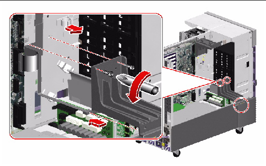
2. Remove the PCI air deflector from the power distribution board bracket.
Pull out the two plastic pins securing the PCI air deflector and remove it from the system.
3. Remove the lower I/O fan tray bracket.
a. Disconnect the fan status cable (P27) from the back of the I/O fan flex circuit.
b. Remove the two Phillips screws securing the lower I/O fan tray bracket to the centerplane.
c. Rotate the lower I/O fan tray bracket out from the system.
d. Place the bracket on an antistatic mat.
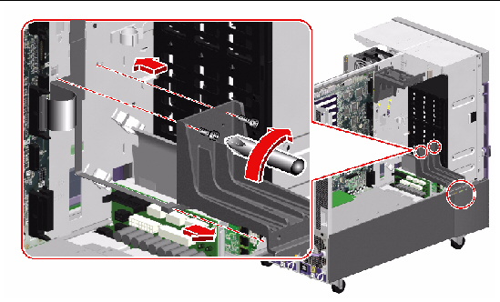
4. Loosen the captive Phillips screw securing the power distribution board to its bracket.
Access the captive screw from the front of the system, through disk drive Slot 3.
5. Carefully pull the power distribution board out from the system until you can easily access the two cable assemblies still attached to the power distribution board.
The power distribution board is held in place by two tabs that fit into cutouts on the chassis sidewall and by one tab on the centerplane.
|
Note - Be careful not to damage the I2C cable and the motherboard power cables still attached to the power distribution board. |
a. Pull the power distribution board out until it clears the tab on the centerplane.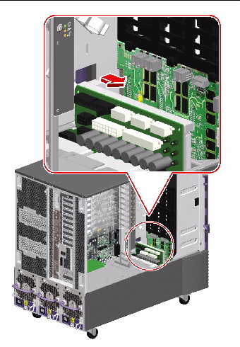
b. Carefully rotate the board away from the power distribution board bracket.
c. Pull the power distribution board out from the system enough so that you can disconnect the two cables still attached to the board.
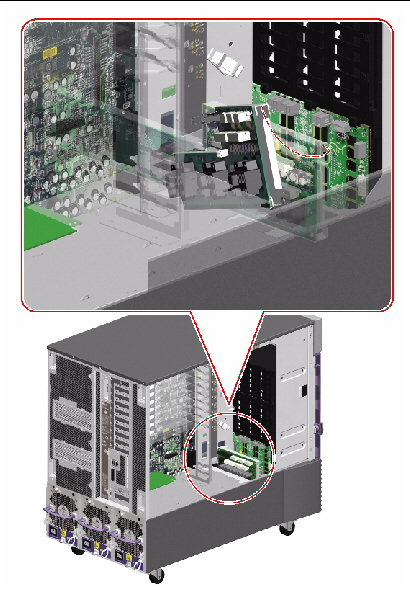
6. Disconnect the following cables from the power distribution board:
a. Motherboard power cables (P7A and P7B) from the power distribution board at connectors P7/J4 and P7/J11(MOTHERBOARD)
b. I/O board remote sense cable (P38) from the power distribution board at connector P38/J10(Sense/5Vstby)
7. Remove the power distribution board from the system.
8. Place the board on an antistatic mat.
To replace the power distribution board, complete this task:
1. Angle the power distribution board into its position in the chassis far enough to still easily access connectors P7/J4 and P7/J11(MOTHERBOARD) and P38/J10(Sense/5Vstby) on the power distribution board.
2. Connect the following cables to the power distribution board:
For cable connector locations, see Cable Connector Locations.
a. Motherboard power cables (P7A and P7B) to the power distribution board at connectors P7/J4 and P7/J11(MOTHERBOARD)
b. I/O board remote sense cable (P38) to the power distribution board at connector P38/J10(Sense/5Vstby)
3. Carefully finish positioning the power distribution board in the chassis against its bracket.
a. Align the board by placing the bracket side of the board against the power distribution board bracket so that the hole on the top of the board aligns with the tab on the centerplane.
This ensures that the tabs on the end of the power distribution board are aligned with their cutouts in the sidewall of the chassis.
b. Slide the board fully into the chassis until the tabs on the end of the power distribution board are in their cutouts on the chassis sidewall and the tab on the centerplane is in the hole on the top of the power distribution board.
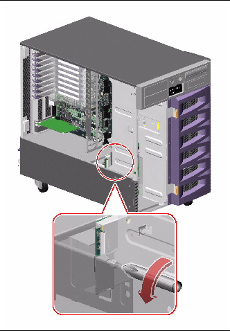
4. Tighten the captive Phillips screw that secures the backplane to the backplane bracket.
Access the captive screw from the front of the system, through disk drive Slot 3.
5. Attach the PCI air deflector to the power distribution board bracket.
a. Align the cutout on the air deflector with the tab on the bracket.
b. Push in the two plastic pins that secure the PCI air deflector to the bracket.
6. Connect the following cables to the power distribution board:
a. I/O board power cable (P13) to the power distribution board at connector P13/J5(I/O BOARD)
b. I/O signal cable (P25) to the power distribution board at connector P25/J9(Signals)
c. RME power cable (P17) to the power distribution board at connector P17/J6(RME)
d. If an expansion backplane is installed, base/expansion cable (P42) to the power distribution board at connector P42/J7(DISKS)
e. Base backplane power cable (P15) to the power distribution board at connector P15/J8(DISKS)
7. Replace the lower I/O fan tray bracket.
a. Connect the fan status cable (P27) to the connector on the back of the I/O fan status flex circuit.
b. Place the lower I/O fan bracket in the system against the centerplane.
Ensure that the ribbon cables behind the lower I/O fan bracket remain flat against the centerplane.
c. Fasten the two Phillips screws that secure the lower I/O fan tray bracket to the centerplane.
To reassemble the system, complete these tasks:
|
Centerplane cutouts P4, P5(I/O fans) Centerplane cutouts P1, P2(CPU fans) |
|||
| Sun Fire V890 Server Service Manual | 817-3957-12 |
Copyright © 2005, Sun Microsystems, Inc. All Rights Reserved.