| Sun Fire V890 Server Service Manual |
| Sun Fire V890 Server Service Manual |
| C H A P T E R 2 |
|
Servicing the Motherboard Side Components |
This chapter describes how to remove and install the system motherboard and components on the motherboard side of the system. For a list of part numbers for field-replaceable units (FRUs) and optional equipment, see Illustrated Parts Breakdown.
The following tasks are covered in this chapter:
You must remove the CPU/Memory board to service the memory modules.

|
Caution - Either a CPU/Memory board or an air baffle must be installed in each CPU/Memory slot at all times. After removing a CPU/Memory board, you must install a replacement board or an air baffle immediately to avoid an automatic thermal shutdown. For more information, see About CPU/Memory Boards. |
|
Note - Use only Sun Fire V890 CPU/Memory boards in the Sun Fire V890 system. |
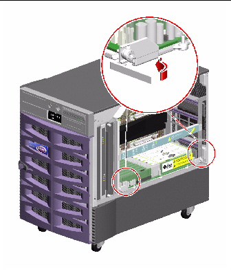
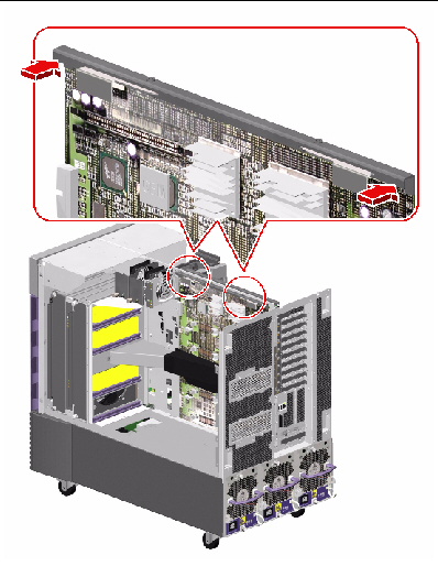
1. Identify the CPU/Memory board that you want to remove.
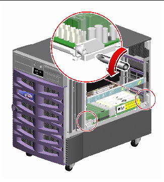
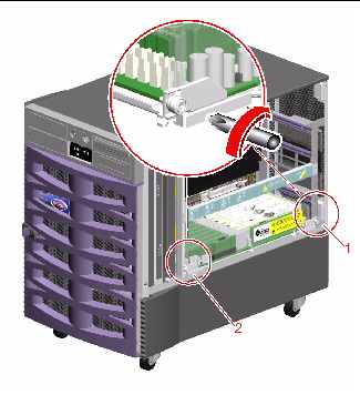
2. Loosen the two captive screws securing the CPU/Memory board.
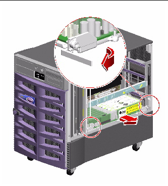
3. Rotate the green CPU/Memory board ejection levers outward so that the CPU/Memory board connectors disengage from the motherboard.
4. Pull the CPU/Memory board from the chassis.
5. Place the CPU/Memory board on an antistatic mat.
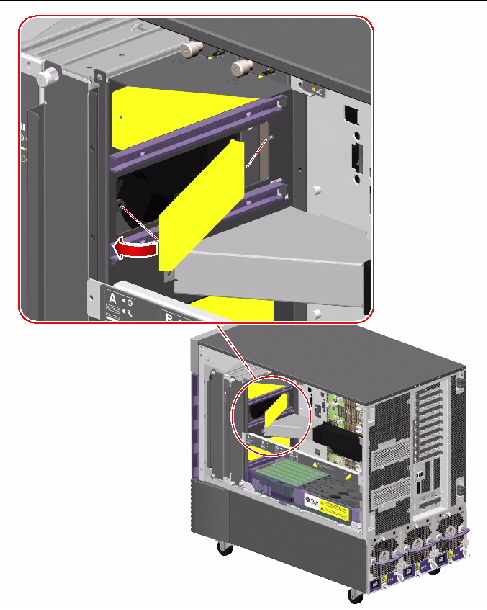
6. If you are not immediately replacing the CPU/Memory board, install a CPU air baffle into its slot next to the CPU fan trays.

|
Caution - A CPU air baffle must be installed into an empty CPU/Memory board slot to ensure proper cooling of the system. Spare CPU air baffles are located under the CPU side chassis top. |
a. Align the air baffle so that the tab on the end is under its slot in the chassis.
b. Rotate the air baffle into position.
c. Push in the plastic pin on the air baffle.
7. If you are not immediately replacing the CPU/Memory board, install a CPU/Memory board dust cover on that slot's motherboard CPU/Memory board connectors.
If you are installing a replacement CPU/Memory board, you must transfer all memory modules from the faulty board to the replacement board. Complete these tasks:
To reassemble the system, complete this task:
If you are not replacing the part right away, you need to perform a reconfiguration boot. A reconfiguration boot is required in order for the operating system to recognize the configuration change. See:
|
Note - Use only Sun Fire V890 CPU/Memory boards in the Sun Fire V890 system. |
If you are replacing a faulty CPU/Memory board with a new one, you must transfer the memory modules from the faulty CPU/Memory board to the new one. See the following sections for more information about transferring memory modules:
1. Locate the CPU/Memory board slot into which you want to install the CPU/Memory board.
2. If a CPU/Memory board connector dust cover is installed on the slot's motherboard CPU/Memory board connectors, remove it.

|
Caution - If you have not removed the dust cover from the motherboard CPU/Memory board connectors, installing a CPU/Memory board in that slot may damage the motherboard and the CPU/Memory board. |
3. If a CPU air baffle is installed in the CPU/Memory board's slot, remove the air baffle.
a. Pull the plastic tab on the air baffle and rotate the baffle from its slot.
b. Place the CPU air baffle into an empty CPU air baffle slot on the underside of the chassis top.
4. Make sure that the green ejection levers on the CPU/Memory board are rotated out at least 90 degrees.
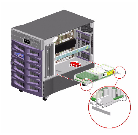
5. Slide the CPU/Memory board into the guides in the chassis.
Slide the board into the system until the connectors on the board begin to engage the sockets on the motherboard and the ejection levers begin to contact the bracket.
6. Push in the two ejection levers simultaneously until the board is fully engaged in its slot.
7. Hand-tighten the two captive screws on the CPU/Memory board.
8. Using a No. 2 Phillips screwdriver, fully tighten the right-side captive screw and repeat for the left-side screw.
To reassemble the system, complete this task:
If you installed this part as a new option, you need to perform a reconfiguration boot. A reconfiguration boot is required in order for the operating system to recognize the new device. See:
Read the section About Memory Modules.
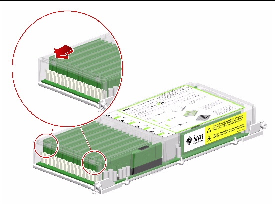
1. Remove the plastic cover on the CPU/Memory board.
Push the tabs inward until you can lift the cover free of the CPU/Memory board shroud.
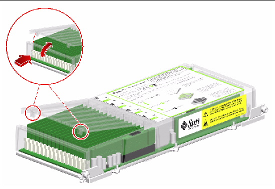
2. Identify the memory module that you want to remove.
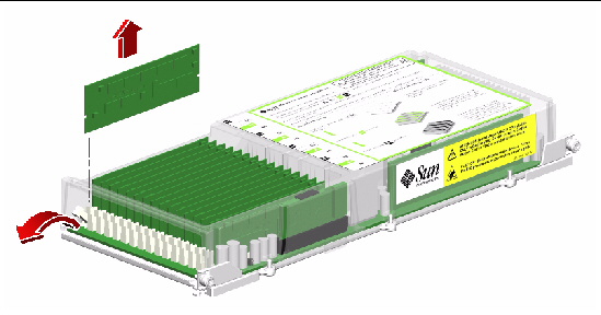
3. Push down on the ejection levers at each end of the memory module until the memory module pops out of its socket.
Apply even pressure on both levers.
4. Grasp the top corners of the memory module and pull it up and out of its socket.
5. Place the memory module on an antistatic mat.
6. If you are not installing replacement memory modules immediately, replace the plastic cover on the CPU/Memory board.
To fully engage the tabs on the cover, push both tabs at the same time until you hear a click.
To replace a memory module, complete this task:
To reassemble the system, complete these tasks:
If you are not replacing the part right away, you need to perform a reconfiguration boot. A reconfiguration boot is required in order for the operating system to recognize the configuration change. See:
Read the section About Memory Modules.
1. Remove the plastic cover on the CPU/Memory board.
Push the tabs inward until you can lift the cover free of the CPU/Memory board shroud.
2. Locate the slot into which you will install the memory module.
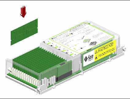
3. Rotate outward the memory module ejection levers for that slot.
4. Holding the bottom edge of the module parallel to its socket, carefully align the module so that each of its contacts is centered on a socket pin.
5. Push firmly and evenly on both ends of the memory module until its bottom edge is firmly seated in the socket.
You will hear a click when the ejection levers are in the locked position.
6. Replace the plastic cover on the CPU/Memory board.
To fully engage the tabs on the cover, push both tabs at the same time until you hear a click.
To reassemble the system, complete these tasks:
If you installed this part as a new option, you need to perform a reconfiguration boot. A reconfiguration boot is required in order for the operating system to recognize the new device. See:
The primary CPU fan tray is in slot 1. If a CPU fan tray fails and you do not have a replacement available, leave the failed CPU fan tray installed to ensure proper system cooling. The failed fan tray acts as a baffle channeling airflow to cool the CPU/Memory module. For more information about CPU fan trays, see About Fan Trays.
All fan trays feature a hot-swap capability. You can remove and replace a faulty fan tray without shutting down the operating system or turning off the system power. For additional details, see About Hot-Pluggable and Hot-Swappable Components.
|
Note - Use only Sun Fire V890 CPU fan trays in the Sun Fire V890 system. |
If you are not performing a hot-swap procedure, complete the following task:
1. Identify the CPU fan tray that you want to remove.
The primary CPU fan tray occupies CPU fan tray slot 1. For information about CPU fan tray LEDs, see About Fan Tray LEDs.
2. Loosen the two captive screws holding the CPU fan tray in the chassis.
3. Slide the fan tray out from the system.

|
Caution - If you are performing a hot-swap procedure, do not put your hand into the empty fan bay. The fans in the populated fan tray are still spinning. |

|
Caution - You must install a replacement fan tray immediately to ensure proper system cooling. |
To replace the CPU fan tray, complete this task:
To reassemble the system, complete this task:
All fan trays feature a hot-swap capability. You can remove and replace a faulty fan tray without shutting down the operating system or turning off the system power. For additional details, see About Hot-Pluggable and Hot-Swappable Components.
|
Note - Use only Sun Fire V890 CPU fan trays in the Sun Fire V890 system. |
If you are not performing a hot-swap procedure, complete the following task:
1. Identify the slot into which you want to install the CPU fan tray.
The primary CPU fan tray occupies CPU fan tray slot 1. For information about CPU fan tray LEDs, see About Fan Tray LEDs.

|
Caution - If you are performing a hot-swap procedure, do not put your hand into the empty fan bay. The fans in the populated fan tray are still spinning. |
2. Align the CPU fan tray with its slot in the chassis.
The arrow label on the fan tray indicates the top side of the fan tray.
3. Slide the fan tray into the chassis until the connector on the fan tray is firmly seated in its socket.
4. Tighten the two captive screws on the fan tray.
To reassemble the system, complete this task:
If you installed this part as a new option while the system was powered off, you need to perform a reconfiguration boot. A reconfiguration boot is required in order for the operating system to recognize the new device. See:
|
Note - The motherboard fan tray is also referred to as the I/O bridge fan tray by the system's firmware and environmental software. For more information about motherboard fan trays, see About Fan Trays. |
All fan trays feature a hot-swap capability. You can remove and replace a faulty fan tray without shutting down the operating system or turning off the system power. For additional details, see About Hot-Pluggable and Hot-Swappable Components.
If you are not performing a hot-swap procedure, complete the following task:
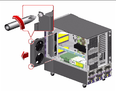
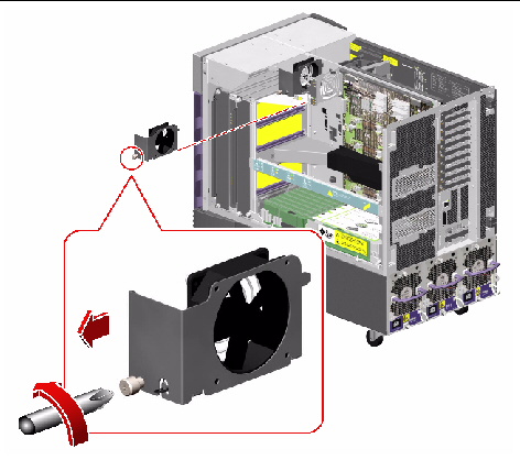
1. Identify the motherboard fan tray that you want to remove.
The primary motherboard fan tray occupies slot 5. The fan tray numbers are stamped into the chassis sheet metal at the base of each fan tray.
2. Unplug the motherboard fan tray cable from the fan tray you are going to remove.
If you are removing a redundant fan tray, drape the cable away from the other fan.

|
Caution - If you are performing a hot-swap procedure, do not put your hand into the empty fan bay. The fan in the populated fan tray is still spinning. |
3. Loosen the captive screw on the fan tray you are going to remove.
4. If you are removing fan tray 5 and fan tray 6 is installed, disconnect the cable to fan tray 6 and drape it out of the way so that you can remove fan tray 5.
5. Slide the fan tray you are removing out of the system.
6. If you disconnected the cable to fan tray 6 to remove fan tray 5, reconnect the cable to fan tray 6.
If you disconnected the cable to fan tray 6 as part of a hot-swap procedure for fan tray 5 and you are immediately replacing fan tray 5, do not reconnect the cable to fan tray 6 until you install fan tray 5.
To replace the motherboard fan tray, complete this task:
To reassemble the system, complete this task:
|
Note - The motherboard fan tray is also referred to as the I/O bridge fan tray by the system's firmware and environmental software. For more information about motherboard fan trays, see About Fan Trays. |
All fan trays feature a hot-swap capability. You can remove and replace a faulty fan tray without shutting down the operating system or turning off the system power. For additional details, see About Hot-Pluggable and Hot-Swappable Components.
If you are not performing a hot-swap procedure, complete the following task:
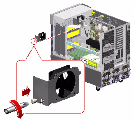
1. Locate the slot into which you will install the motherboard fan tray.
a. If you are installing fan tray 5 and fan tray 6 is installed, disconnect the cable to fan tray 6.
The primary motherboard fan tray occupies slot 5. The fan tray numbers are stamped into the chassis sheet metal at the base of each fan tray.
|
Note - Ensure that the fan tray cable is not in the path of the fan tray that you will install. |
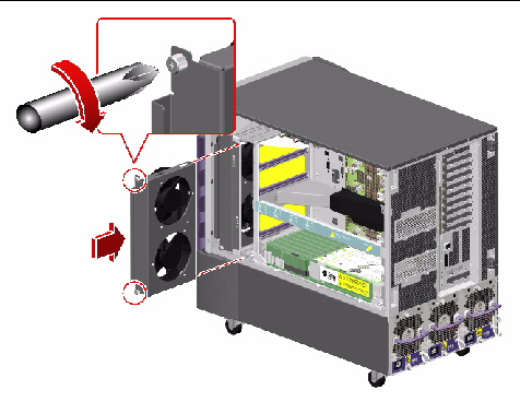
2. Align the fan tray to be installed with its plastic guide in the chassis.
3. Slide the fan tray into the chassis.
4. If you disconnected the cable to fan tray 6 to install fan tray 5, reconnect the cable to fan tray 6.

|
Caution - If you are performing a hot-swap procedure, do not put your hand into the empty fan bay. The fan in the populated fan tray is still spinning. |
5. Tighten the captive screw on the fan tray.
6. Connect the motherboard fan tray cable to its connector.
To reassemble the system, complete this task:
If you installed this part as a new option while the system was powered off, you need to perform a reconfiguration boot. A reconfiguration boot is required in order for the operating system to recognize the new device. See:
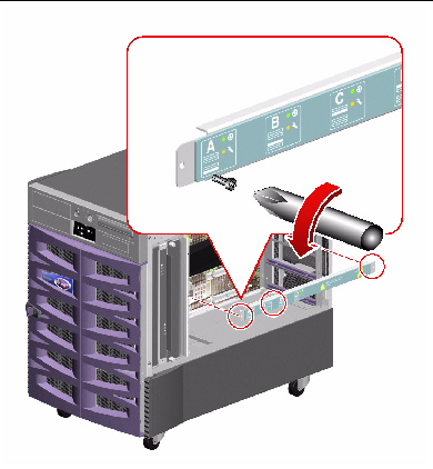
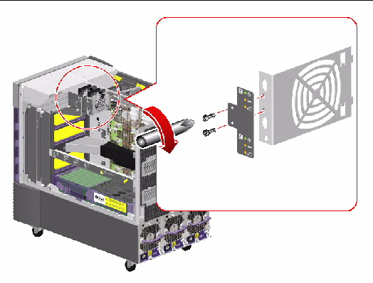
1. Disconnect the CPU fan status cable from the top of the assembly.
Press the tab on the cable connector.
2. Remove the two Phillips screws securing the assembly to the chassis.
3. Carefully pull the fan status assembly out of the system and place it on an antistatic mat.
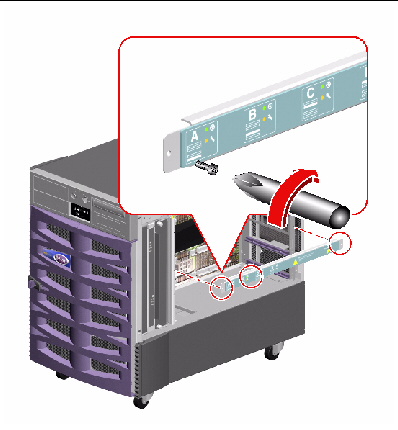
To replace the CPU fan status assembly, complete this task:
1. Position the fan status assembly into place in the system.
The CPU fan status cable connector is on the top of the assembly. The sheet metal bracket is keyed on the bottom so that you can install the assembly only one way.
2. Fasten the two Phillips screws that attach the assembly to the chassis.
3. Connect the fan tray status cable to the assembly.
To reassemble the system, complete this task:
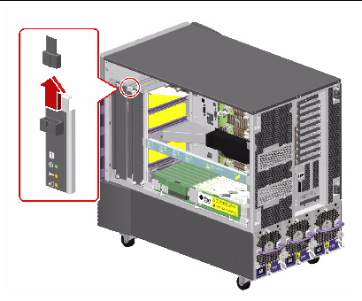
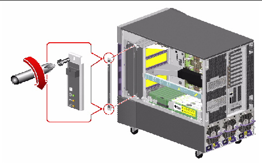
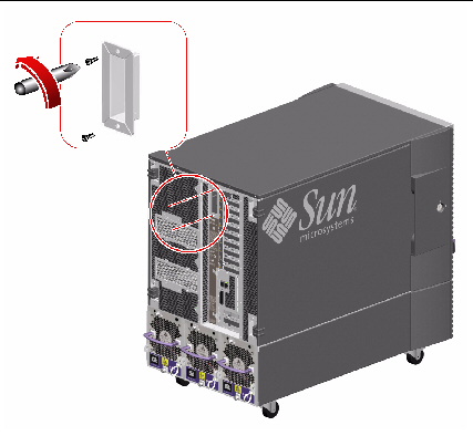
1. Remove the two Phillips screws securing the status assembly to the chassis.
Be sure to support the status assembly as you remove the screws so that the ribbon cable connected to the back of the assembly is not jarred.
2. Disconnect the ribbon cable from the connector on the status assembly and remove the assembly from the system.
3. Place the status assembly on an antistatic mat.
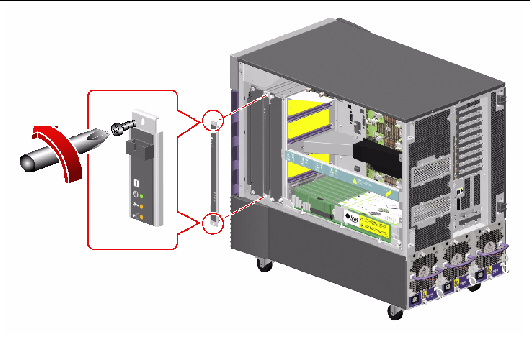
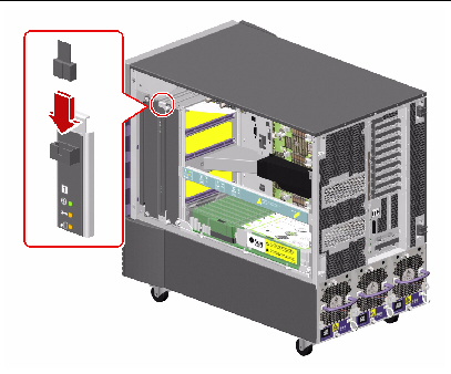
To replace the CPU/Memory board status assembly, complete this task:
1. Connect the CPU/Memory board status cable to the connector on the back of the status assembly.
2. Place the status assembly into position and fasten the two Phillips screws that secure the assembly to the chassis.
To reassemble the system, complete this task:
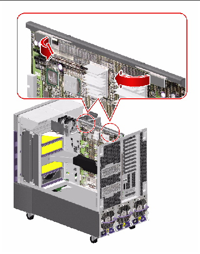
1. Disconnect the motherboard fan status cable from the back of the flex circuit.
2. Remove the two Phillips screws securing the flex circuit to the bracket.
3. Remove the flex circuit from the system.
4. Place the flex circuit on an antistatic mat.
To replace the motherboard fan status flex circuit, complete this task:
1. Position the flex circuit in the system and fasten the two Phillips screws that secure it to its bracket.
2. Connect the motherboard fan status cable to the connector on the back of the flex circuit.
To reassemble the system, complete this task:
1. Disconnect the CPU/Memory board status assembly cable (P35) from the motherboard at connector P35 (LED).
2. Disconnect the motherboard power cable (P8) from the motherboard at connector J4702 (Main Power).
3. Disconnect the motherboard power cable (P9) from the motherboard at connector J4701 (48 Volt Power).
4. Disconnect the base backplane FC-AL cable (A and B) from the motherboard at connectors A(FCALIN) and B(FCALOUT).
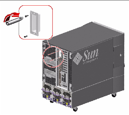
5. Remove the Gigabit Ethernet housing from the rear panel.
Remove the two Phillips screws securing the housing to the chassis rear panel.
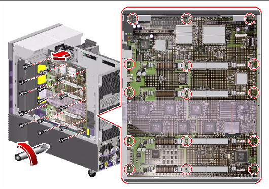
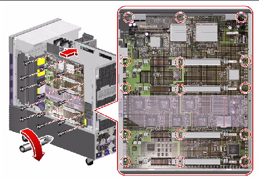
6. Remove the 15 M4 Phillips screws securing the motherboard to the centerplane.
7. If the system I/O board is installed, disengage the motherboard from the system by rotating the two ejection levers away from the motherboard.
8. Remove the motherboard from the system.
a. Carefully pull the motherboard away from the centerplane so that the plastic motherboard air duct slides off the metal motherboard air guide.
b. Angle the motherboard to avoid the motherboard fan status flex circuit as you pull the motherboard out from the system.
9. Place the motherboard on an antistatic mat.
10. Transfer the CPU/Memory board connector dust covers from the replacement motherboard to the faulty motherboard.
To replace the motherboard, complete this task:
1. If you are installing a new motherboard, remove the CPU/Memory board connector dust covers from every slot into which you will install a CPU/Memory board.
Keep dust covers on any unused slots.
2. Carefully position the motherboard in the chassis against the centerplane.
a. Angle the motherboard into the system so that you do not hit the motherboard fan status assembly.
b. Carefully slide the plastic motherboard air duct over the metal motherboard air guide.
c. Use the two guideposts that fit through two holes near the top of the motherboard to align the motherboard against the centerplane.
3. If the system I/O board is installed, seat the motherboard in the system by evenly and firmly pushing on the top outer ends of the motherboard stiffener and ejection assembly.

|
Caution - Do not push on the ejection levers to seat the motherboard in the system. |
4. Replace the 15 M4 Phillips screws that secure the motherboard in the chassis.
a. Insert the top center screw and tighten it by two turns.
b. Insert the screw directly beneath the top center screw and tighten it by two turns.
c. Insert the top left and right screws and tighten them by two turns.
d. Repeat this pattern for the remaining screws until they are all installed.
e. Fully tighten the screws in the pattern described until the board is fully seated.
5. Replace the two Phillips screws that secure the Gigabit Ethernet connector housing to the rear panel.
6. Connect the motherboard power cable (P8) to the motherboard at connector J4702 (Main Power).
7. Connect the motherboard power cable (P9) to the motherboard at connector J4701 (48 Volt Power).
8. Connect the base backplane FC-AL cable (A and B) to the motherboard at connectors A(FCALIN) and B(FCALOUT).
9. Connect the CPU/Memory board status assembly cable (P35) to the motherboard at connector P35.
To reassemble the system, complete these tasks:
| Sun Fire V890 Server Service Manual | 817-3957-12 |
Copyright © 2005, Sun Microsystems, Inc. All Rights Reserved.