| Sun Fire V890 Server Service Manual |
| Sun Fire V890 Server Service Manual |
| C H A P T E R 1 |
|
Preparing to Service the System |
This chapter tells you what you need to know about preparing for and completing service procedures.
|
Note - Except for removing and installing power supplies and disk drives, this system must be serviced only by qualified service personnel. |
Please be sure to keep the following guidelines in mind:
The following tasks are covered in this chapter:
The following information is also included:
Do not use this power-on procedure if the operating system is already installed and you have just added a new internal option or external storage device. To power on the system after adding one of these options, see:

|
Caution - Never move the system when the system power is on. Movement can cause catastrophic disk drive failure. Always power off the system before moving it. |

|
Caution - Before you power on the system, make sure that the front and side doors and all plastic outer panels are properly installed. |
1. Turn on power to any peripherals and external storage devices.
2. Turn on power to the alphanumeric terminal or local graphics console, if present.
3. Insert the system key into the front panel keyswitch and turn it to the Normal or Diagnostics position.
Normal position will enable the custom OpenBootTM configuration for diagnostic testing as defined for your system.
Diagnostics position will enable the standard default OpenBoot configuration for running diagnostic tests. Your system will automatically run maximum POST and OpenBoot Diagnostics tests and display the output. The system will also enable automatic system recovery (ASR).
For information about the standard default Open Boot configuration for diagnostic testing, refer to the OpenBoot PROM Enhancements for Diagnostic Operations Guide, which is included on the Sun Fire V890 Documentation CD.
See About Power Button and Keyswitch Settings for information about each keyswitch setting.
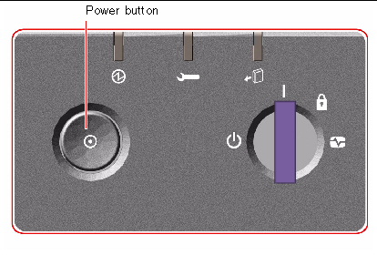
4. Press the Power button to the left of the keyswitch to power on the system.
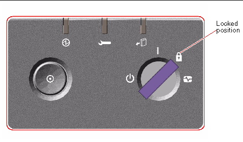
5. Turn the keyswitch to the Locked position.
This prevents anyone from accidentally powering off the system.
6. Remove the key from the keyswitch and keep it in a secure place.
The system's front panel LED indicators provide power-on status information. For more information about the system LEDs, see About Front Panel LEDs.
If your system encounters a problem during system startup, and the keyswitch is in the Normal position, try restarting the system in the Diagnostics mode to determine the source of the problem. Turn the front panel keyswitch to the Diagnostics position and power cycle the system. See:
1. Notify users that the system will be powered down.
2. Back up the system files and data, if necessary.
3. Ensure that the front panel keyswitch is in the Normal or Diagnostics position.
4. Press and release the Power button on the system front panel.
The system begins a graceful software system shutdown.
5. Wait for the front panel Power/OK LED to turn off.
6. Turn the keyswitch to the Forced Off position.
7. Remove the key from the keyswitch and keep it in a secure place.
Sun Fire V890 systems feature a variety of components that can be serviced while the machine is running.
Hot-pluggable components are components that a qualified service technician can install or remove while the system is running, without affecting the rest of the system's capabilities. However, in many cases, you must prepare the operating system prior to the hot-plug event by performing certain system administration tasks.
Components that can be serviced without such preparation are called hot-swappable components. These components can be removed or inserted at any time without preparing the operating system in advance.
Sun Fire V890 hot-pluggable components fall into three basic groups:
Each group is discussed in more detail in the sections that follow.
|
Note - PCI and disk hot-plug operations are not supported when the system ok prompt is displayed. You can only perform these hot-plug operations while the operating system is running. |
Sun Fire V890 fan trays and power supplies are hot-swappable--they can be removed or inserted at any time without requiring prior software preparations. Keep in mind that a power supply is not considered hot-swappable unless it is part of an N+1 redundant power configuration--a system configured with the third power supply. Do not remove a power supply from a working system if its removal would leave the system with fewer than two working power supplies.
You can install or remove a power supply or fan tray while the system is operating at the ok prompt. However, in the case of the power supply, you must issue a reset-all command at the ok prompt in order for the change to be recognized the next time the operating system is booted.

|
Caution - When hot-swapping a redundant fan tray, do not put your hand into the empty fan tray bay. The fans in the populated bay are still spinning. |
For additional information, see:
Sun Fire V890 internal disk drives are hot-pluggable. However, certain software preparations are required. To perform Sun Fire V890 disk drive hot-plug operations, you use the Solaris luxadm utility. The luxadm utility is a command-line tool for managing intelligent storage arrays such as Sun StorEdgeTM A5x00 series disk arrays or Sun Fire V890 internal storage arrays.
For more information about luxadm, refer to the Sun Fire V890 Server Owner's Guide. For complete disk hot-plug procedures, refer to Platform Notes: Using luxadm Software, which is available on the Sun Fire V890 Documentation CD. Refer also to the Sun Fire V890 Server Product Notes for late-breaking details.

|
Caution - When hot-plugging a disk drive, after disconnecting the drive from its backplane, allow 30 seconds or so for the drive to spin down completely before removing it from its drive bay. |
On Sun Fire V890 systems, PCI cards are hot-pluggable, while the system controller card cannot be serviced when the machine is running.
Hot-plug operations for PCI cards involve Dynamic Reconfiguration (DR). DR is an operating system feature that provides the ability to reconfigure system hardware while the system is running. DR lets you logically attach or detach hardware resources within an active operating system. The main benefit of DR is that a service provider can add or replace hardware resources with little or no impact on normal system operations.
PCI card hot-plug procedures may involve software commands for preparing the system prior to removing a device, and for reconfiguring the operating system after installing a new device. In addition, certain system requirements must be met in order for hot-plug operations to succeed.
For information about system requirements and limitations, and for detailed PCI card hot-plug procedures, refer to the Sun Fire V890 Dynamic Reconfiguration User's Guide, which is available at http://docs.sun.com, under Solaris on Sun Hardware. Refer to the Sun Fire V890 Server Product Notes for late-breaking details.
There are two different methods for performing PCI hot-plug operations on Sun Fire V890 systems:
The push-button method relies on push buttons and status LEDs located near each PCI slot. You can initiate a hot-plug operation by pressing the push button for the corresponding slot. The command-line method lets you perform hot-plug operations via a remote login session, a Remote System Control (RSC) console, or a locally attached console. This method involves the Solaris cfgadm(1) command.
Both hot-plug methods make use of the status LEDs located near each PCI slot. These LEDs indicate where and when it is safe to insert or remove a card, and also show whether the operation has succeeded or failed. For additional details on hot-plug status LEDs, see About PCI Slot LEDs.
For detailed PCI hot-plug procedures, refer to the Sun Fire V890 Dynamic Reconfiguration User's Guide, which is available at http://docs.sun.com, under Solaris on Sun Hardware. Refer to the Sun Fire V890 Server Product Notes for late-breaking details.
After installing any new internal option or external storage device, you must perform a reconfiguration boot so that the operating system is able to recognize any newly installed devices. In addition, if you remove any device and do not install a replacement device prior to rebooting the system, you must perform a reconfiguration boot in order for the operating system to recognize the configuration change. This requirement also applies to any component that is connected to the system's I2C bus, including memory modules, CPU/Memory boards, and power supplies.
This requirement does not apply to any component that is:

|
Caution - All internal options (except disk drives and power supplies) must be installed only by qualified service personnel. |


|
Caution - Before you power on the system, make sure that the front and side doors and all plastic outer panels are properly installed. |
You need a system console in order to issue software commands. See:
1. Turn on power to any peripherals and external storage devices.
Read the documentation supplied with the device for specific instructions.
2. Turn on power to the console.
3. Insert the system key into the front panel keyswitch and turn the keyswitch to the Diagnostics position.
4. Press the Power button to the left of the keyswitch to power on the system.
The system will automatically run power-on self-test (POST) and OpenBoot Diagnostics tests and display the output.
5. When the diagnostics tests are completed, and the system banner is displayed on the system console, immediately abort the boot process to access the system ok prompt.
The system banner contains the Ethernet address and host ID.
The env-on command re-enables the OpenBoot environmental monitor, which may have been disabled as a result of the abort key sequence. The boot -r command rebuilds the device tree for the system, incorporating any newly installed options so that the operating system will recognize them.
7. Turn the keyswitch to the Locked position, remove the key, and keep it in a secure place.
This prevents anyone from accidentally powering off the system.
The system's front panel LED indicators provide power-on status information. For more information about the system LEDs, see About Front Panel LEDs.
If your system encounters a problem during system start-up, and the keyswitch is in the Normal position, try restarting the system with the keyswitch in the Diagnostics position to determine the source of the problem. Turn the front panel keyswitch to the Diagnostics position and power cycle the system.
The system Power button is recessed to prevent accidentally turning the system on or off. The ability of the Power button to turn the system on or off is controlled by the security keyswitch.
If the operating system is running, pressing and releasing the Power button initiates a graceful software system shutdown. Pressing and holding in the Power button for five seconds causes an immediate hardware shutdown.
|
Note - Whenever possible, you should use the graceful shutdown method. Forcing an immediate hardware shutdown may cause disk drive corruption and loss of data. Use this method only as a last resort. |
The four-position security keyswitch controls the power-on modes of the system and prevents unauthorized users from powering off the system or reprogramming system firmware. The following table describes the function of each keyswitch setting.
To install your server or to diagnose problems, you need some way to enter system commands and to view system output. There are four ways to do this.
1. Attach an alphanumeric (ACSII) character terminal to serial port A.
You can attach a simple terminal to serial port A. For instructions, see How to Initiate a Reconfiguration Boot.
2. Establish a tip connection from another Sun system.
For information about establishing a tip connection, refer to the OpenBoot 4.x Command Reference Manual, which is available at http://docs.sun.com, under Solaris on Sun Hardware. Refer to the Sun Fire V890 Server Product Notes for late-breaking details.
3. Install a local graphics console on your server.
The server is often shipped without a mouse, keyboard, monitor, or frame buffer for the display of graphics. To install a local graphics console on a server, you must install a graphics frame buffer card in a PCI slot, and attach a monitor, mouse, and keyboard to the appropriate rear panel ports. For detailed instructions, see How to Configure a Local Graphics Console.
|
Note - Power-on self-test (POST) messages are output to serial port A (ttya) or the RSC console only. |
4. Set up a Remote System Control (RSC) console.
RSC is a remote server management tool that lets you monitor and control your server over serial lines or over a network. RSC provides remote system administration for geographically distributed or physically inaccessible systems. For additional details, refer to your Sun Fire V890 Server Owner's Guide.
If your server is configured without a local graphics console, you need to attach an alphanumeric (ASCII) terminal to the server in order to install the operating system and to run diagnostic tests. Alternatively, you can install a local graphics console, create a tip connection from another Sun system, or set up an RSC console. See:
|
Note - You cannot use an RSC console to perform the initial installation of the Solaris OS. The Solaris OS must be installed prior to setting up an RSC console. |
1. Connect a DB-25 null modem serial cable or a DB-25 serial cable and null modem adapter to the terminal's serial port.
2. Connect the opposite end of the cable to the system's serial port connector or to serial port A on the serial splitter cable.
3. Connect the terminal's power cable to an AC outlet.
4. Set the terminal to receive:
See the documentation accompanying your terminal for more information.
You can now issue system commands and view system messages. Continue with your installation or diagnostic procedure as needed.
If your server is configured without a local alphanumeric terminal, you need to install a local graphics console in order to install the operating system and to run diagnostic tests. Alternatively, you can attach an alphanumeric (ASCII) terminal, create a tip connection from another Sun system, or set up an RSC console. See:
|
Note - You cannot use an RSC console to perform the initial installation of the Solaris OS. The Solaris OS must be installed prior to setting up an RSC console. |
To install a local graphics console, you must have:
1. Install the graphics card into a vacant PCI slot.
See How to Install a PCI Card.
2. Attach the monitor video cable to the graphic card's video port.
Tighten the thumbscrews to secure the connection.
3. Connect the monitor's power cord to an appropriate AC power outlet.
4. Attach the keyboard cable to one of the system's USB ports.
5. Attach the mouse cable to the system's remaining USB port, or to a USB port on the keyboard, if applicable.
You can now issue system commands and view system messages. Continue with your service or diagnostic procedure as needed.
If you are not performing a hot-plug procedure, complete the following task:
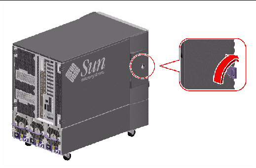
1. Use the system key to unlock the door.
3. To remove the door from the chassis, open the door 90 degrees and pull it up until its mounting pins clear the brackets on the rear panel.
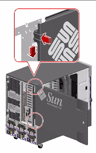
To reassemble the system side door, complete the following task:
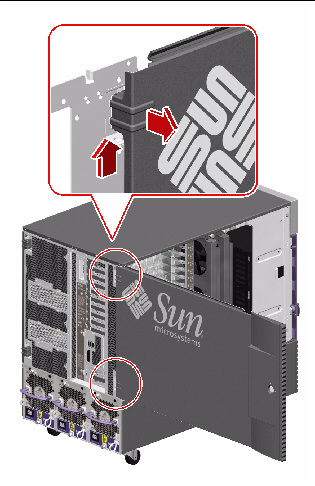
1. If you removed the side door, remount it to the chassis.
Position the side door mounting pins over the corresponding holes in the chassis rear panel and lower the side door into place.
Make sure that the door is firmly seated in its frame.
3. Lock the side door with the system key.
The following figure shows the system features that are accessible from the rear panel.
A grounding screw is located just above the center power supply. When installing a a Sun Fire V890 server into a rack, or connecting the server to an external storage array, be sure to connect an appropriate grounding strap between the server's grounding screw and the grounding screw on the rack enclosure or external storage array. A grounding strap prevents ground loops between systems and peripherals and helps guard against possible data loss.
Use the following procedure to prevent static damage whenever you are accessing any of the internal components of the system.
Complete this task if you are working with a component that is not hot-pluggable:
You must have the following items:
1. Disconnect the AC power cord from the wall power outlet only when performing the following procedures:
The AC power cord provides a discharge path for static electricity, so it should remain plugged in except when you are servicing the parts noted above.
2. Use an antistatic mat or similar surface.
When performing any option installation or service procedure, place static-sensitive parts, such as boards, cards, and disk drives, on an antistatic surface. The following items can be used as an antistatic surface:
3. Use an antistatic wrist strap.
Attach one end of the strap to the system chassis sheet metal, and attach the other end to your wrist. Refer to the instructions that come with the strap.
|
Note - Make sure that the wrist strap is in direct contact with the metal on the chassis. |

4. Detach both ends of the strap after you complete the installation or service procedure.
The following tools are required to install and service the system:
The latter two items help protect the server against damage due to electrostatic discharge. For more information, see How to Avoid Electrostatic Discharge.
| Sun Fire V890 Server Service Manual | 817-3957-12 |
Copyright © 2005, Sun Microsystems, Inc. All Rights Reserved.