| C H A P T E R 7 |
|
Powering the Server On and Off |
This chapter gives instructions on powering the Netra CT server on and off.
|
Note - You can also power the Netra CT server on and off through the alarm card using software commands. Refer to the Netra CT Server System Administration Manual for more information. |
One way to power on and off your server is to log in to the server either remotely, where you would log in to the Netra CT server as root through another server on the network, or directly, where you would connect a terminal console directly to your Netra CT server. A terminal console can be an ASCII terminal, workstation, or PC laptop.
For a direct login, the connection you use varies depending on the Netra CT server model you have, the type of terminal console you are using, and the card that you are connecting to:
|
1. Get the appropriate cable(s) and adapter(s) and make the necessary connections.
You may need one or more cables and adapters in order to connect the ASCII terminal to the server. The cables and adapters you need varies, depending on the model server you have and the card that you are connecting to.
|
|||||
|
|
|||||
|
2. Access the "Set Up Menu" of the ASCII terminal and bring up the Serial Communications section.
3. Set up the serial port communications parameters.
The default settings should match the values reported on the host serial port.
Verify that communication has been established to the server and the keyboard/display of the ASCII terminal.
|
1. Get the appropriate cable(s) and adapter(s) and make the necessary connections.
You may need one or more cables and adapters in order to connect a Solaris workstation to the server. The cables and adapters you need varies, depending on the model server you have and the card that you are connecting to.
|
|||||
|
|
|||||
|
2. Check the /etc/remote file for the appropriate line.
To connect to the TTY A or COM 1 port on the workstation, check for this line:
3. Type tip hardwire at the prompt.
You should see the word connected as the response.
To disconnect the tip window, type ~. (tilde period) at the prompt.
|
1. Get the appropriate cable(s) and adapter(s) and make the necessary connections.
You may need one or more cables and adapters in order to connect a PC laptop to the server. The cables and adapters you need varies, depending on the model server you have and the card that you are connecting to.
|
|||||
|
|
|||||
|
2. Set the following connection parameters:
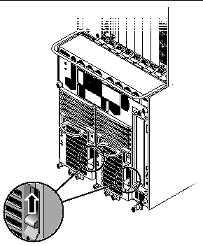
1. Verify that the power supply locking mechanism(s) on the server you are about to power on are in the locked ( ), or down, positions (FIGURE 7-1).
Make sure you lock both power supplies if you are powering on a Netra CT 810 server.

When the power supply locking mechanism is locked, the green LED on the power suppl(ies) flash, indicating that the power suppl(ies) are powered on, but the server has not been powered on yet. Also, the PDU LEDs on the system status panel should be in this state:
This tells you that the power supply locking mechanism(s) are in the locked (down) position and the power distribution unit(s) are receiving power and functioning properly.
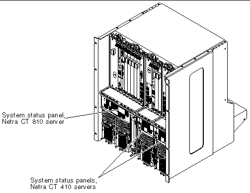
2. Locate the system status panel.
The location of the system status panel in the Netra CT 810 server and Netra CT 410 server is illustrated in FIGURE 7-2.

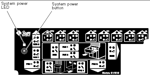
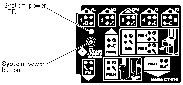
3. Locate the system power button on the system status panel and press the system power button to power on the server.
FIGURE 7-3 shows the system power button location for the Netra CT 810 server, and FIGURE 7-4 shows the system power button location for the Netra CT 410 server.
When you first power-on the Netra CT server, some or all of the green Power LEDs on the system status panel flash on and off for several moments.


4. Verify that the system power LED on the system status panel is on, indicating that the system is completely powered on.
FIGURE 7-3 shows the system power LED location for the Netra CT 810 server, and FIGURE 7-4 shows the system power LED location for the Netra CT 410 server.
5. Verify that the green power ( ) LED on the power supplies are on, indicating that they are powered on and functioning properly.
6. If you have a Netra CT 410 server, connect an external DVD drive to your server.
Refer to Appendix A for more information.
7. Insert the Solaris operating environment DVD into the DVD drive.
Refer to Connecting a Terminal Console to the Server for instructions on connecting a terminal to your server, if necessary.
9. Boot up the server through the DVD drive.
You can power off the Netra CT server one of three ways, depending on the terminal hookup and the state of the host CPU:
1. In preparation for bringing down the operating system and powering down the server, ensure that all significant application activity is quiesced on the server.
Refer to Connecting a Terminal Console to the Server for more information.
3. Determine if you are at the OpenBoot (ok) prompt.
When the server is finished shutting down, the ok prompt is displayed.
5. Go to the front of the Netra CT server and locate the power supply unit(s).
6. Determine if the green power ( ) LED on the power supply unit(s) are blinking.
7. If you want to completely power off the Netra CT server, push the purple power supply unit locking mechanism(s) up into the unlocked ( ) position (see FIGURE 7-1).
|
Note - You must unlock the locking mechanism on both power supply units on the Netra CT 810 server in order to completely power off that server. |
The green power ( ) LED(s) on the power supply unit(s) should go off (unlit), indicating that the system is now completely powered off.
1. In preparation for bringing down the operating system and powering off the server, ensure that all significant application activity is quiesced on the server.
2. Go to the front of the Netra CT server and locate the system status panel.
The location of the system status panels in the Netra CT 810 server and Netra CT 410 server is illustrated in FIGURE 7-2.
3. Locate the system power button on the system status panel.
FIGURE 7-3 shows the system power button location for the Netra CT 810 server, and FIGURE 7-4 shows the system power button location for the Netra CT 410 server.
4. Press the system power button and release it to go through a graceful hardware power-down.
This will start the orderly power-down sequence in a manner that no persistent OS data structures are corrupted. In the orderly power-down, applications in service may be abnormally terminated and no further services will be invoked by the CPU. The system power LED will blink for several seconds, then it will go off.
5. Wait for several moments, then verify that the green power ( ) LED(s) on the power supply unit(s) are blinking, indicating that the system is in the standby mode.
FIGURE 7-3 shows the system power LED location for the Netra CT 810 server, and FIGURE 7-4 shows the system power LED location for the Netra CT 410 server.
6. If you want to completely power off the Netra CT server, push the purple power supply unit locking mechanism(s) up into the unlocked ( ) position (see FIGURE 7-1).
|
Note - You must unlock the locking mechanism on both power supply unit(s) on the Netra CT 810 server in order to completely power off that server. |
The green power ( ) LED(s) on the power supply unit(s) should go off (unlit), indicating that the system is now completely powered off.
Copyright © 2004, Sun Microsystems, Inc. All rights reserved.