| C H A P T E R 2 |
|
Chassis Description |
The Netra CT 820 server provides OEM equipment designers with carrier-grade, standards-based, high availability solutions built on the PCI Industrial Computer Manufacturer's Group (PICMG) 2.16 specification. This high-capacity platform features 18 node slots and a redundant infrastructure (switching fabric board, management, power, and cooling), making it ideal for carrier-grade telecom and Internet applications. Beyond its high availability features, the Netra CT 820 server is highly modular, scalable, and serviceable.
Hot-swappable system components provide built-in redundancy to simplify replacement and minimize service time. Redundant distributed management cards enable customers to manage multiple processor boards and conduct chassis diagnostics remotely for enhanced system reliability. Two 6U slots are reserved for PICMG 2.16 switching fabric boards. The Netra CT 820 server routes Ethernet signals across the midplane without the use of cables, saving time in setup, maintenance, and repair, and eliminating the thermal challenges of traditional cabling methods.
The PICMG 2.16 specification defines the CompactPCI Packet Switching Backplane. The Netra CT 820 server sends all Ethernet signals across the midplane. By moving system traffic from the shared bus architecture to a fault-tolerant switched midplane, overall system throughput can be vastly increased while retaining the reliability and hot-swap capacity of cPCI.
The Netra CT 820 server accommodates dual redundant switching fabric boards and node boards.
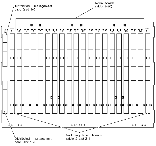
The Netra CT 820 server midplane features 21 6U slots. Slot 1 is dedicated to two 3U distributed management cards (slots 1A and 1B). Slots 2 and 21 are dedicated to 6U PICMG 2.16-compliant switching fabric boards. Slots 3 through 20 are PICMG 2.16-compliant node slots.
All slots support IEEE 1101.11-style, 80 mm-deep transition cards in the rear-panel I/O section directly behind the midplane.
Central office power plants are based on redundant high-availability -48V DC power. AC power delivered by the public utility is rectified to DC and stored in battery systems, which in turn supply the equipment. Equipment is fed from two sets of power feeds.
Increasingly, these feeds are being provided by independent power plants. In environments with independent power plants, the two feeds must be completely isolated from one another.

|
Caution - It is imperative that these feeds never join. Failure to properly design a chassis's power input subsystem could result in voltage transference, system damage, or safety issues. |
The Netra CT 820 server is designed specifically to meet the increasing requirements of the telco environment and central office. The Netra CT 820 server delivers a highly redundant 2N power system, including dual power domains on the midplane. The system minimizes the impact caused by failures of power feeds, power supplies, the midplane, or the cooling subsystems.
The Netra CT 820 server implements dual power domains. Each power domain is powered from 2N redundant power supplies with 2N redundant power inputs. FIGURE 2-2 illustrates how power is distributed within the Netra CT 820 server.
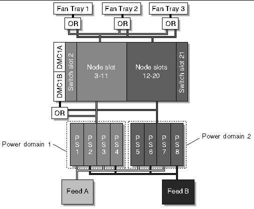
There are two redundant power feeds: A and B. Each power feed provides input to two power supplies in each of the two power trays. As shown in FIGURE 2-2, feed A provides power to the odd-numbered power supplies while feed B provides power to the even-numbered power supplies.
This configuration provides 2+2 redundant power to each power domain. The system is designed to continue operation with any single fault. Examples of faults include:
If a single power feed fails, each domain continues to receive power from the two power supplies powered from the healthy feed. If a single power supply fails, each domain continues to receive adequate power from the healthy power supplies. If a power domain fails, the other power domain is unaffected. A power domain might fail if pins get bent, creating a short between two voltage rails or between a voltage rail and ground.
TABLE 2-1 shows the effects of various types of power faults with 250W power supplies.
Note that the redundant power feeds are kept isolated from one another. The feeds are not diode-ORed together. This is important for telco facilities that provide redundant power plants, because a diode failure could allow faults in one power plant to affect the other power plant.
A power switch is provided on the back of the chassis. This switch disables the output from all eight power supplies.
To properly budget for power consumption within the Netra CT 820 server, many factors need to be considered. These factors include:
See the information in this section for the power consumption of the switching fabric boards, distributed management cards, and fan trays.
The Netra CT 820 server has two power domains. Each power domain is powered from four power supplies in a 2N redundant configuration.
Each power domain receives input power from redundant power feeds. Each redundant power feed provides input power to half the power supplies within the power domain. Power budgets should assume that only half of the provided power supplies in each domain are operational when faults are present. For example, a system with four power supplies per power domain only has two operation supplies in each power domain if a DC input feed has failed. See Power Distribution Overview for more information about the effects of faults on the power subsystem.
Power budgeting must account for the power supply capabilities for each of the four voltage levels (3.3V, 5V, +12V, and -12V). For a system using eight 250W hot-swap DC power supplies, the power supplies can provide the following currents for each voltage level:
|
Max
|
Max
|
||||
|---|---|---|---|---|---|
|
3.3V[2] |
|||||
|
5V1 |
|||||
As new power supplies are introduced with higher power outputs, more redundant power and current can be delivered to the chassis.
The distributed management cards and fan trays draw power from both power domains. Under normal conditions, each domain provides approximately 50% of the power for these shared components. Power budgets for each domain should provide for at least 50% of the necessary distributed management card and fan tray power. Due to tolerances of the ORing diodes and the voltage levels, it is likely that slightly more than 50% of the power will be drawn from the domain with the higher voltage. If this causes a slight over-current situation, that voltage will drop until the ORing diodes automatically balance the load between the two domains.
Note that in the event of a power domain failure, 100% of the distributed management card and fan tray power is drawn from a single domain. However, the healthy domain has a complete set of power supplies (assuming only single failures); that is, 50% is drawn from the "budget" supplies and 50% from the "redundant spare" supplies.
The Netra CT 820 server is designed to cool a maximum of 20W per distributed management card slot, 40W per node slot, and 60W per switching fabric board slot. Unused slots must be covered with a filler panel to properly maintain the cooling in other slots.
The following topics specify the various interfaces for the chassis's power input subsystem.
DC input power is provided through two DC line filters. These filters are labeled A and B. Each filter has three terminals: -48V DC, Return, and chassis ground. The
-48V DC and Return terminals are designed for connection with #10 ring terminals, and the chassis ground terminal is designed for connection with a 1/4-inch ring terminal.
The A and B connections provide redundant input power to both power trays. For full redundancy, these connections must:
Circuit breakers should be rated based on maximum load at minimum voltage with one failed feed. The circuit breakers cannot be rated for more than 60A under any circumstance.
Each DC power input includes an EMI filter to reduce line-conducted emissions.
Refer to the Netra CT 820 Server Installation Guide for more information about connecting DC power to the Netra CT 820 server.
Two power trays occupy the bottom of the Netra CT 820 server. Each tray has its own backplane that provides slots for four power supplies.
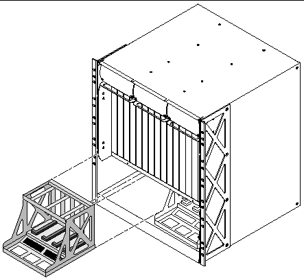
The Netra CT 820 server is designed for use with the 3U by 8HP CompactPCI power supplies that comply with the PICMG 2.11 Power Interface Specification R1.0 that are designed specifically for use with the Netra CT 820 server.
The Netra CT 820 server uses 250W DC power supplies. These supplies provide non-IPMI management features (DEG#, FAIL#, and INH#). For information on removing and replacing the power supplies, refer to the Netra CT 820 Server Service Manual.
The Netra CT 820 server power supply is a hot-swappable, CompactPCI power supply using a standard Positronic 47-pin connector that is fully compliant with the PICMG 2.11 Power Interface Specification. High current density enables this unit to deliver up to 40A on both the +5V and +3.3V outputs combined. Remote sense and active current share on the +5V, +3.3V, and +12V outputs, along with ORing FETs, allow these units to be used in redundant, hot-swap applications.
The Netra CT 820 server's power distribution architecture includes dual power domains and ORed management power to central resources. FIGURE 2-4 illustrates power distribution on the midplane.
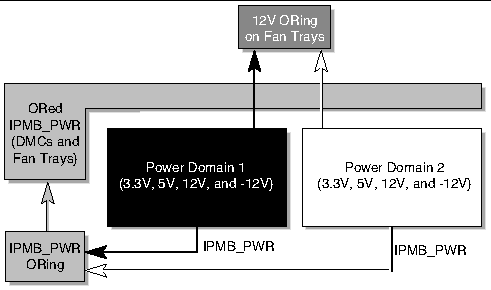
The Netra CT 820 server's midplane implements two independent power domains for the CompactPCI slots. FIGURE 2-2 shows the power domains.
Power domain 1 includes slots 2 through 11. One switching fabric board is installed in slot 2 and node boards can be installed in slots 3 through 11. Power domain 1 is powered from power tray 1.
Power domain 2 includes slots 12 through 21. One switching fabric board is installed in slot 21 and node boards can be installed in slots 12 through 20. Power domain 2 is powered from power tray 2.
Both power domains are cooled and managed by common, redundant fan trays and chassis management modules. These common components receive management power by ORing the two domains' IPMB_PWRs together. The IPMB_PWR ORing diodes are on the midplane. The fan tray blowers are powered by ORing +12V from both power domains. These ORing diodes are physically located in the fan trays.
The Netra CT 820 server uses three hot-swappable fan trays to cool the chassis. Each fan tray includes three blowers. FIGURE 2-5 illustrates the airflow through the platform.
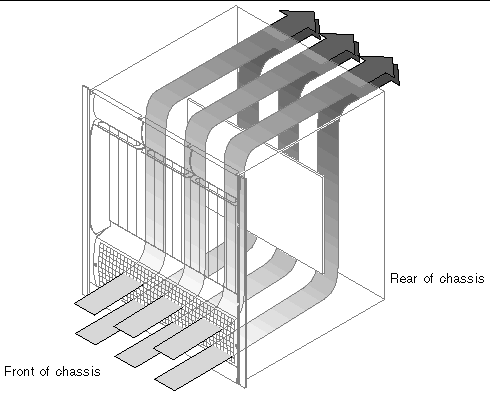
Each of the Netra CT 820 server's three fan trays is a modular, field-replaceable unit. Each tray contains three blowers, a control board, and a status LED. These features are discussed in the following sections.
Each fan tray contains three DC brushless blowers for a total of nine blowers in a Netra CT 820 server. Each blower has a two-phase, four-pole motor. The following table lists blower specifications:
The fan tray includes a control board for fan tray management. The control board provides the following features:
On insertion or initial power-up, the fan control board stages power to the blowers. The first blower is enabled immediately. The second blower is enabled about 300 ms after the first, and the third blower is enabled about 300 ms after the second. Each blower is independently protected using a self-resetting positive temperature co-efficient (PTC) component.
The control board also includes logic to set the LED to the "unhealthy" state if any of the blowers drop below approximately 1000 rpm, or if onboard voltage is invalid. The distributed management card can also force the LED to the "unhealthy" state.
Each fan tray provides a health/status LED on its front panel. TABLE 2-8 lists the different LED states:
An air intake grill with a replaceable air filter is attached to the bottom front of the Netra CT 820 server. The grill must be removed to replace the filter. The grill must also be removed to access the system's power supplies.
Copyright © 2004, Sun Microsystems, Inc. All rights reserved.