| Netra CT 820 Server Product Overview
|
   
|
Distributed Management Card Description
|
The distributed management cards are 3U, single-slot cards that plug into slots 1A and 1B in the Netra CT 820 server. They provide centralized management and alarming for up to 21 slots, as well as for system power supplies and fans.
The distributed management card is essentially a special-purpose single-board computer with its own CPU, memory, operating system, and peripherals. The distributed management card monitors and configures IPMI-based components in the chassis. When thresholds (such as temperature and voltage) are crossed or a failure occurs, the distributed management card captures these events, stores them in an event log, sends SNMP traps, and drives the telco alarm relays and alarm LEDs. The distributed management card can query FRU information (such as serial number, model number, and manufacture date), detect presence of components (such as fan tray and CPU board), and perform health monitoring of each component. In addition, the distributed management card controls the power-up sequencing of each device (except the fan trays), and the power to each slot through the BD_SEL# signal.
Distributed Management Card Features
- High-density 3U x 1-slot form factor
- Compatible with PICMG 2.1, 2.16, and 2.9-compliant components
- Manages through the Intelligent Platform Management Bus (IPMB) protocol
- Supports failover from the active distributed management card to the standby card
- Provides isolated IPMI signals for each slot for maximum security and reliability
- Out-of band management interface through the rear transition card
- Hot-swap support for IPMI-based field-replaceable components
- DB15 alarm interface through the rear transition card
- Critical, Major, and Minor alarm LEDs at the front panel
- Status and hot-swap LEDs at the front panel
- Monitors backplane voltages and status for up to eight power supplies
- Monitors system temperature sensors
- Monitors system fan tray presence
- Monitors tachometers for up to 16 system fans
Distributed Management Card Ports and LEDs
The Netra CT 820 server is available only as a rear-access server, so most of the cabling for the distributed management card will be to the rear transition card at the rear of the server. The only exception would be the console port on the distributed management card at the front of the server. You can administer the Netra CT 820 server either from the front of the server, through the console port on the distributed management card, or from the rear of the server, through one of the two console ports on the rear transition card.

|
Caution - Do not attempt to administer the Netra CT 820 server through the console ports on both the distributed management card and the rear transition card at the same time. No mechanism is provided to disable simultaneous input from the front and rear cards, so attempts to input data from both ports will place the boards in an unknown state.
|
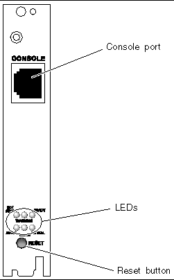
FIGURE 3-1 shows the console port and LEDs on the distributed management card. TABLE 3-1 describes the functions of the console port, and TABLE 3-2 describes the functions of each LED.
FIGURE 3-1 Distributed Management Card Ports

TABLE 3-1 Distributed Management Card Port Functions
|
Port
|
Function
|
|
Console
|
This port is used to remotely administer the Netra CT 820 server using the Netra CT 820 server software. Refer to the Netra CT 820 Server Software Administration Manual for more information.
|
TABLE 3-2 Distributed Management Card LED Functions
|
LED
|
Function
|
|
HOT SWAP
|
- Off - The card is up and running. Do not remove the distributed management card in this state.
- On - The card is powered off. It is safe to remove the distributed management card in this state.
|
|
WARNING
|
Reserved for future use.
|
|
READY
|
- Off - The card is not ready.
- On - On the active distributed management card, this signals that the card has booted and is fully powered up and running.
- Blinking - On the standby distributed management card, this signals that the card has booted and is fully powered up and running.
|
|
MINOR
|
- Off - No alarm has been triggered.
- On - A minor event has been triggered.
|
|
MAJOR
|
- Off - No alarm has been triggered.
- On - A major event has been triggered.
|
|
CRITICAL
|
- Off - No alarm has been triggered.
- On - A critical event has been triggered.
|
There is also a Reset button at the base of the distributed management card. This button is used to perform a hard reset of the distributed management card. You should use this button to perform a hard reset of the distributed management card only if you cannot go through a graceful shutdown of the system.
|
Note - By default, the top distributed management card (labeled 1A) will be the active management card after the initial chassis power-on, and the bottom card (labeled 1B) will be the standby management card. After a hardware or software failover event, the standby distributed management card will become the active card and take over all of the management services in the chassis. For more information about distributed management card failover, and what hardware and software events cause failovers, refer to the Netra CT 820 Server System Administration Guide (817-2647).
|
Rear Transition Card for the Distributed Management Card
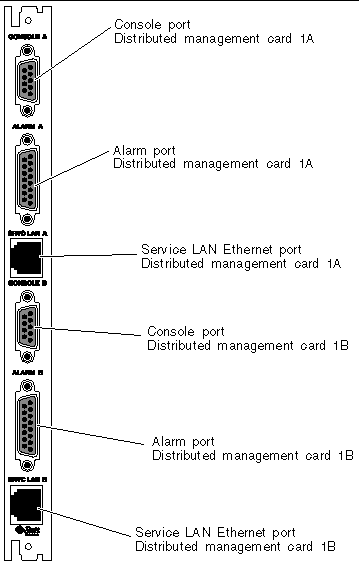
The rear transition card is used to route the signals from the distributed management cards installed in slots 1A and 1B at the front of the server to ports in the rear transition card installed at the rear of the server. FIGURE 3-2 shows the ports on the rear transition card for the distributed management cards.
FIGURE 3-2 Ports on the Rear Transition Card for the Distributed Management Card

See TABLE 3-3 for a description of the functions of each of the ports used in the rear transition card.
TABLE 3-3 Port Functions of the Rear Transition Card for the Distributed Management Card
|
Port
|
Function
|
|
Console
|
This port is used to remotely administer the Netra CT 820 server using the Netra CT 820 server software. Refer to the Netra CT 820 Server Software Administration Manual for more information.
|
|
Alarm
|
This port transmits alarm signals to external systems (dry-contact relay).
|
|
Service LAN Ethernet
|
This port provides a Service LAN Ethernet connection.
|
| Netra CT 820 Server Product Overview
|
817-2643-11
|
   
|
Copyright © 2004, Sun Microsystems, Inc. All rights reserved.

