| C H A P T E R 4 |
|
Switching Fabric Board Description |
The Netra CT 820 server is available only as a rear-access server, so all of the cabling for the switching fabric board will be to the rear transition card at the rear of the server. There are no active components on the rear transition card, so you must have the accompanying switching fabric board installed in the same slot at the front of the server, even though no cables will be connected to that front card. However, you will use the LEDs on the switching fabric board installed in the front of the system to check the status and fault conditions on the board.
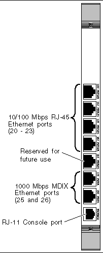
The rear transition card is connected to the switching fabric board through the midplane through the J3 and J5 CompactPCI connectors. This card is used to route Ethernet traffic through four 10/100-megabit switched Ethernet MDIX ports through shielded RJ-45 connectors (ports 20-23), two 1000-megabit Ethernet MDIX ports (ports 25-26), and an RJ-11 console port.
|
Note - Port 24 on the rear transition card for the switching fabric board is reserved for future use. |
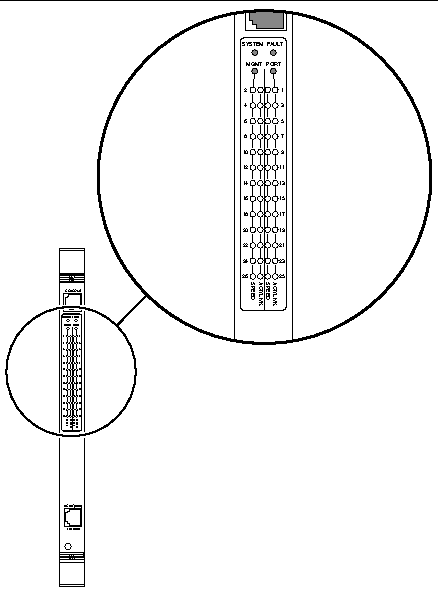
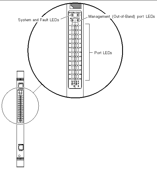
FIGURE 4-1 shows the location of the LEDs on the switching fabric board. FIGURE 4-2 shows the ports on the rear transition card for the switching fabric board.


Two LEDs provide board-level system status information.
On power-up, the System LED is yellow. After the basic board integrity checks are complete, the System LED changes to green.
The System LED normally remains green unless a board failure is detected. A board failure turns the System LED off. The System LED could also be off if the board is in a fault state. See TABLE 4-1.
The Fault LED is off unless a serious internal error is detected. If a serious error is detected the red Fault LED turns on. To turn off the Fault LED once it is illuminated, the switching fabric board must be powered off. Refer to the Netra CT 820 Server Service Manual for instructions on powering off a single slot in the server. See TABLE 4-2 for more detail on the Fault LED.
The status of all Ethernet ports (including the out-of-band management port) is indicated by LEDs visible from the front panel. A green LED is used to indicate link and activity (transmit or receive), and a yellow LED is used to indicate the current port speed. See TABLE 4-3 and TABLE 4-4.
TABLE 4-5 explains how the LED port numbers on each switching fabric board map out to the physical card slots in the Netra CT 820 server.
The switching fabric board provides 10/100-megabit Ethernet ports and 1000-megabit Ethernet ports interconnected through a fully meshed 9-Gbps switching fabric. An 802.1D bridge relay entity exists between any pair of switched ports. The switched Ethernet ports offer low-latency, wire-speed switching performance on all ports simultaneously. The switching fabric board supports 8192 (8K) MAC address entries (simultaneously) in its filtering database.
The switching fabric board provides a logical link control (LLC) interface between the IP stack of the embedded onboard operating system and the switched ports. This interface allows for sending and receiving frames to and from the onboard CPU and any of the switched Ethernet ports. This capability allows the onboard CPU to be a presence on the attached network and allows external clients to manage the operation of the switch through any of the switched Ethernet ports.
One 10BASE-T/100BASE-TX unswitched Ethernet port is provided on the switching fabric board for switch management purposes. This port conforms to all requirements of the IEEE 802.3 (CSMA/CD) MAC interface.
This port does not have a MAC relay entity between itself and any of the switched Ethernet ports. This separation makes it possible to allocate all switched ports to users while always maintaining a secure and available path to manage the switch.
The switching fabric board provides an LLC interface between the IP stack of the embedded onboard operating system and the out-of-band Ethernet port. This interface allows sending and receiving frames to and from the onboard CPU and the out-of-band Ethernet port. This capability allows the onboard CPU to be a presence on the attached network and allows external clients to manage the operation of the switch through the out-of-band Ethernet port.
The out-of-band Management port provides access to a separate subnet from that of the switched ports. The switching fabric board must be provided with an IP address for each LLC interface that is to be enabled. If the out-of-band Ethernet interface is to be used, it must be assigned an IP address and subnet mask combination that place the interface in a separate subnet from that of the switched ports.
The switching fabric board supports a pair of extensions to the standard Spanning Tree protocol that enhance its utility in building fault-tolerant networks. The standard Spanning Tree protocol supports redundant links for resiliency, but the algorithm that selects the active link can take anywhere from 30 to 50 seconds to converge. This delay often causes application layer timeouts.
The switching fabric board addresses this problem with two extensions to the Spanning Tree protocol: Fast Uplink and Fast Port.
Fast Uplink enables a redundant pathway toward the root bridge to be quickly selected upon failure of link integrity on the current path to the root bridge. The switchover time is typically less than one second.
Fast Port enables the user to select ports that do not need to participate in the Spanning Tree protocol. These ports must have simple client stations attached to them and must not provide a path to any device that might act as a bridge between LAN segments. That is, the user must ensure that no bridges or routers can be accessed through a port that has Fast Port turned on. When Fast Port is turned on, the port does not participate in Spanning Tree and does not undergo or cause any Spanning Tree topology changes.
The switching fabric board offers the ability to limit forwarding of broadcasts, multicasts, and frames with unknown destination MAC addresses (flooding). The user can set a maximum frame rate forwarded by the switch for these traffic types. This feature prevents malfunctioning network equipment from flooding the network.
The embedded diagnostic functions of the switching fabric board ensure virtually faultless operation both at initialization and continuously during switch operation. The In-System verification includes Power-On Confidence (POC) tests and Online Integrity tests.
Power-On Confidence (POC) tests are diagnostic tests run when the switching fabric board is booted. The POC test suite includes only those diagnostic tests that do not affect externally attached devices. When running POC tests, the switching fabric board becomes available to the user within 150 seconds of a power-on or reset. All subsystems are included in the POC suite.
These are tests that are run on a continuous basis while the switching fabric board is in service. Online Integrity tests are enabled by default, but the switching fabric board also provides a method to disable them.
The integrity tests operate continuously during execution of application code to detect hardware faults. Upon detecting a fault, the switching fabric board can take itself out of service. All attached clients will lose link.
A hardware watchdog timer removes the switching fabric board from service if it is not refreshed periodically by the CPU. This guards against CPU failure. If the watchdog timer expires, link will be deasserted on all external ports, and the switching fabric board will be reset. The user can configure the board to reboot after a watchdog event or to remain offline.
The switching fabric board's implementation of the System Management Bus (SMB) conforms to PICMG 2.9, the specification that defines SMB in the CompactPCI environment. The SMB utilizes the I2C bus hardware layer coupled with Intelligent Platform Management software. The Intelligent Platform Management Interface specification enables system components on the I2C hardware layer bus to communicate with the distributed management card, thereby making possible "out-of-band" management of a system's resources, with an emphasis on controlling hot-swap activities.
Copyright © 2004, Sun Microsystems, Inc. All rights reserved.