A P P E N D I X  B

Signal Pinouts

This appendix gives the pinouts for the server rear ports and identifies connectors on various server boards. Topics include:


B.1 Gigabit Ethernet Ports

The server has four autonegotiating 10/100/1000BASE-T Gigabit Ethernet system domain ports. All four Ethernet ports use a standard RJ-45 connector, the transfer rates for which are given in TABLE B-1. FIGURE B-1 shows the pin numbering of the ports. TABLE B-2 describes the pin signals.


TABLE B-1   Ethernet Connection Transfer Rates
Connection Type IEEE Terminology Transfer Rate
Ethernet 10BASE-T 10 Mbit/sec
Fast Ethernet 100BASE-TX 100 Mbits/sec
Gigabit Ethernet 1000BASE-T 1000 Mbit/sec

FIGURE B-1   Gigabit Ethernet Port Pin Numbering

Figure showing Gigabit Ethernet ports.


TABLE B-2   Gigabit Ethernet Port Signals
Pin Signal Description Pin Signal Description
1 Transmit/Receive Data 0 + 5 Transmit/Receive Data 2 –
2 Transmit/Receive Data 0 – 6 Transmit/Receive Data 1 –
3 Transmit/Receive Data 1 + 7 Transmit/Receive Data 3 +
4 Transmit/Receive Data 2 + 8 Transmit/Receive Data 3 –


B.2 Network Management Port

The server has one 10BASE-T Ethernet management domain interface, labelled NET MGT.



electrical icon

Caution - If you are planning to use the network management (NET MGT) port, you must use a shielded Ethernet cable to maintain your server’s NEBS compliance. The cable’s shield must be grounded at both ends.


FIGURE B-2   Network Management Port Pin Numbering

Figure showing the network management port.


TABLE B-3   Network Management Connector Signals
Pin Signal Description Pin Signal Description
1 Transmit Data + 5 Common Mode Termination
2 Transmit Data – 6 Receive Data –
3 Receive Data + 7 Common Mode Termination
4 Common Mode Termination 8 Common Mode Termination


B.3 Serial Ports

The server has two serial ports, labeled SERIAL MGT and TTYA. TABLE B-4 lists the default serial connection settings for both serial ports.


TABLE B-4   Default Serial Connection Settings 
Parameter Setting
Connector SERIAL MGT or l0l0l
Rate 9600 baud
Parity None
Stop bits 1
Data bits 8

B.3.1 Serial Management Port

The serial management connector (labeled SER MGT) is an RJ-45 connector that can be accessed from the rear panel. This port is the default connection to the server. Use this port only for server management.


electrical icon

Caution - You must use a shielded Ethernet cable to maintain your server’s NEBS compliance. The cable’s shield must be grounded at both ends.


FIGURE B-3 shows the pin numbering of the serial management port. TABLE B-5 describes the pin signals.
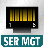
FIGURE B-3   Serial Management Port Pin Numbering

Figure showing the serial management port.


TABLE B-5   Serial Management RJ-45 Connector Signals
Pin Signal Description Pin Signal Description
1 Request to Send 5 Ground
2 Data Terminal Ready 6 Receive Data
3 Transmit Data 7 Data Set Ready
4 Ground 8 Clear to Send

If you need to connect to the SERIAL MGT port using a cable with either a DB-9 or a DB-25 connector, use a supplied adapter to perform the crossovers given for each connector. The supplied RJ-45 to DB-9 and RJ-45 to DB-25 adapters are wired as described in TABLE B-6 and TABLE B-7.

B.3.1.1 RJ-45 to DB-9 Adapter Crossovers


TABLE B-6   RJ-45 to DB-9 Adapter Crossovers 
Serial Port (RJ-45 Connector)

DB-9 Adapter

Pin Signal Description Pin Signal Description
1 RTS 8 CTS
2 DTR 6 DSR
3 TXD 2 RXD
4 Signal Ground 5 Signal Ground
5 Signal Ground 5 Signal Ground
6 RXD 3 TXD
7 DSR 4 DTR
8 CTS 7 RTS

B.3.1.2 RJ-45 to DB-25 Adapter Crossovers


TABLE B-7   RJ-45 to DB-25 Adapter Crossovers
Serial Port (RJ-45 Connector)

DB-25 Adapter

Pin Signal Description Pin Signal Description
1 RTS 5 CTS
2 DTR 6 DSR
3 TXD 3 RXD
4 Signal Ground 7 Signal Ground
5 Signal Ground 7 Signal Ground
6 RXD 2 TXD
7 DSR 20 DTR
8 CTS 4 RTS

B.3.2 Serial Port TTYA

The port labeled TTYA accepts a DB-9 connector. Use this port for general purpose serial data transfers. FIGURE B-4 shows the pin numbering of the serial port. TABLE B-8 describes the pin signals.
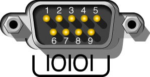
FIGURE B-4   Serial Port (TTYA) Pin Numbering

Figure showing the serial port


TABLE B-8   Serial Port (TTYA) Connector Signals
Pin Signal Description Pin Signal Description
1 Data Carrier Detect 6 Data Set Ready
2 Receive Data 7 Request to Send
3 Transmit Data 8 Clear to Send
4 Data Terminal Ready 9 Ring Indicate
5 Ground    


B.4 Alarm Port

The alarm port on the alarm rear transition module uses a standard DB-15 connector. In a telecommunications environment, use this port to connect to the central office alarming system. FIGURE B-5 shows the pin numbering of the alarm port. TABLE B-9 describes the pin signals.


Note - The alarm port relay contacts are rated for 100V 0.2A maximum.


FIGURE B-5   Alarm Port Pin Numbering

Figure showoing the alarm port


TABLE B-9   Alarm Connector Signals
Pin Service Pin Service
1 NC 9 ALARM1_NC
2 NC 10 ALARM1_COM
3 NC 11 ALARM2_NO
4 NC 12 ALARM2_NC
5 ALARM0_NO 13 ALARM2_COM
6 ALARM0_NC 14 ALARM3_NO
7 ALARM0_COM 15 ALARM3_COM
8 ALARM1_NO CHASSIS FRAME GND


B.5 USB Ports

The server has two USB ports for attaching supported USB 1.1 compliant devices. FIGURE B-6 shows the pin numbering of the USB ports. TABLE B-10 describes the pin signals.

FIGURE B-6   USB Ports Pin Numbering

Illustration of the USB ports.


TABLE B-10   USB Connector Pin Signals
Pin Signal Description
1 +5 V
2 DAT-
3 DAT+
4 Ground