Connecting a Single Chassis with a Single SSC
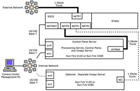
This section illustrates the topology of a single-chassis single-SSC I-Fabric, and provides the procedure for connecting the I-Fabric components.
The SSC must be installed in chassis slot SSC0 for a single chassis, single SSC configuration. The Provisioning Server software cannot configure and provision the server blades if the SSC is installed in SSC1.
Figure 3–3 Single Chassis With a Single SSC and no External Switch

 To Connect A Single Chassis With a Single SSC to the Control
Plane Server
Steps
-
Connect the NETMGT port of SSC0 to the eri0 port of the control plane server with 100 base T copper Ethernet cable.
-
Connect the NETP0 port of SSC0 to the ce0/skge0 port of the control plane server with 1000 base T copper Ethernet cable.
-
Connect the NETP7 port of SSC0 to the external network with 1000 base T copper Ethernet cable. Farms are accessed through the NETP7 connection.
-
Connect the eri1 port of the control plane server to your internal network switch with 100 base T copper Ethernet cable.
-
Connect the Control Center Management PC NIC port to the internal network switch.
The type of cable depends on the capacity of the PC NIC and the network switch ports.
-
If you have chosen to install the image server as a separate machine, connect the image server ports as follows.
-
Connect the NETP1 port of SSC0 to the NIC port of the image server machine
Use a cable appropriate for the type of interface card installed in the image server: 100 base T copper for a 10/100 base T NIC, and 1000 base T copper for a gigabyte-capable NIC.
Note –If you have chosen to install the N1 image server on a separate machine, install a gigabyte-capable card such as the Sun GigaSwift NIC or the SysKonnect NIC in the image server machine.
-
If you have a separate image server machine, connect the eri0 port of the image server to your internal network switch with 100 base T copper Ethernet cable.
-
- © 2010, Oracle Corporation and/or its affiliates
