| C H A P T E R 1 |
|
Hardware Installation and Startup |
Before performing any procedures, become familiar with the physical orientation and features of your Sun FireTM V20z or Sun Fire V40z server, including the front and back panels. Refer to the Sun Fire V20z and Sun Fire V40z Servers--User Guide for detailed information about the server.
After unpacking your server, perform the following tasks, which are described in the documentation as indicated:
1. Add any PCI expansion cards or hardware options that you want to install. Refer to the Sun Fire V20z and Sun Fire V40z Servers--User Guide or the documentation shipped with the hardware option for instructions on removing and replacing the system cover and installing the option.
2. If desired, install the server in a rack using orderable slide-rails. See Installing the Server Into a Rack.
3. Connect all cables and power cords. Refer to Cabling of this guide.
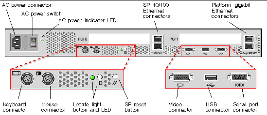
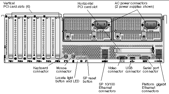
4. Connect your peripherals. Refer to FIGURE 1-8 of this guide for an illustration of the server's back panel connector ports.
5. Power on and boot the server as described in Powering On and Booting the Server of this guide.
6. Perform initial software setup as described in Chapter 2 of this guide.
7. Configure your server to customize it for your use. Refer to the Sun Fire V20z and Sun Fire V40z Servers--Server Management Guide for details.
For the most up-to-date user documentation, for both the Sun Fire V20z and Sun Fire V40z servers, please visit the following Web site:
http://www.sun.com/products-n-solutions/hardware/docs/
Servers/Workgroup_Servers/Sun_Fire_V20z/index.html
This site contains the user manuals, the Release Notes and the individual guides for each of the customer-replaceable units (CRUs).
To verify whether a document on the site is more recent than the document that you have, refer to the final two digits (the dash-roll) of the Part Number for that document.
|
Note - A document explaining the differences among the released versions of the Sun Fire V20z and Sun Fire V40z servers is also available at this Web site. Refer to part number (PN) 817-7185. |
You can safely connect the Sun Fire V20z and Sun Fire V40z servers to an IT Power System.
 The use of the "exclamation-point-in-a-triangle" symbol on the product indicates a reference to the following important safety information, concerning National Deviations for Finland, Norway and Sweden:
Use the following procedure to install the server into a rack using slide-rails.

|
Caution - Before you power on a Sun Fire V40zserver for the first time, you must remove the packaging inserts from the server's PCI card slots and CPU card slot to ensure proper air flow and cooling. You can discard these packaging inserts, which serve as protection during shipping. See Powering On and Booting the Serverfor instructions on removing the inserts. Do NOT remove the plastic air-baffle inserts from the PCI slots.
|
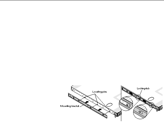
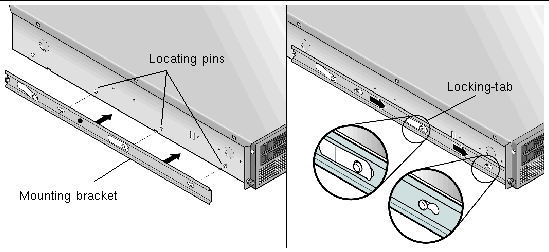
1. Install one mounting bracket to each side of the server as shown in FIGURE 1-1 or FIGURE 1-2.
Position the three holes in the mounting bracket over the front three locating pins on the server's side and push forward on the mounting bracket until the middle locking-tab clicks over the middle pin.
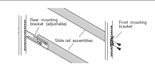
2. Install one slide-rail assembly to each side of the rack as shown in FIGURE 1-3, securing them with the screws provided.
The end of the rail with the adjustable bracket must be positioned toward the back of the rack as shown.
|
Note - Leave the middle screw holes on each front mounting bracket open for the thumb screws on the server. |
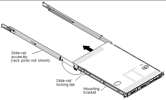
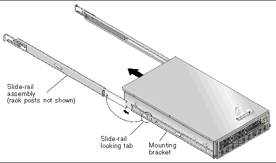
3. Slide the server, with mounting brackets installed, into the rack so that the mounting bracket bases fit inside the slide rail assemblies (see FIGURE 1-4 or FIGURE 1-5).
As you slide the server into the rack, press down on the outer slide-rail locking-tab to allow the mounting bracket to pass through.
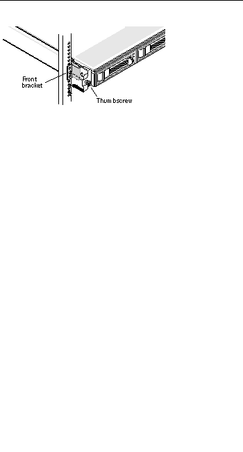
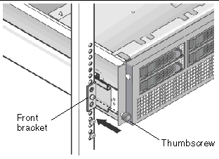
4. With the server pushed into place in the rack, tighten the captive thumbscrews on the server front by screwing them into the middle hole on the slide-rail assembly front bracket (see FIGURE 1-6 or FIGURE 1-7).
Connect cables to the rear of the server as follows. See FIGURE 1-8 or FIGURE 1-9 for the locations of the connector ports on your server.
1. Connect the keyboard cable to the keyboard connector.
2. Connect the mouse cable to the mouse connector.
3. Connect a video monitor cable to the video connector.
VGA multisynch monitors are supported with these servers.
|
Note - Keyboard, mouse and video are optional with an operating system that supports headless operation. |
4. Connect Ethernet cables to the service processor (SP) connectors and the platform gigabit connectors.
See Daisy-Chaining the Servers for information about interconnecting servers and connecting them to a LAN.
5. Connect the AC power cord(s) to the AC power connector(s).
It is important to note the labelling of the Ethernet ports on the back panel of the Sun Fire V20z server. As shown on the far right side of the server illustrated in FIGURE 1-8, interfaces eth1 and eth0 are labelled as "1" on the upper port and "0" on the bottom port, respectively.
The PCI slots are labelled on the server back panel as PCI O (next to the power supply) and PCI 1 (between the SP and platform ethernet ports). See FIGURE 1-8.
It is important to note the labelling of the ethernet ports on the back panel of the Sun Fire V40z server. Referring to the platform gigabit (Gb) ethernet ports at the right edge of the chassis (see FIGURE 1-9), the lower ethernet interface is eth0 andthe upper interface is eth1, respectively.
You can interconnect multiple servers in different daisy-chain configurations by using the SP connectors to form a management LAN as shown in FIGURE 1-10, FIGURE 1-11 and FIGURE 1-12. The figures also show how the servers are connected to external LANs using the platform gigabit connectors.
|
Note - Sun Microsystems recommends that you use cross-over cables of at least one meter in length for daisy-chaining the servers. |
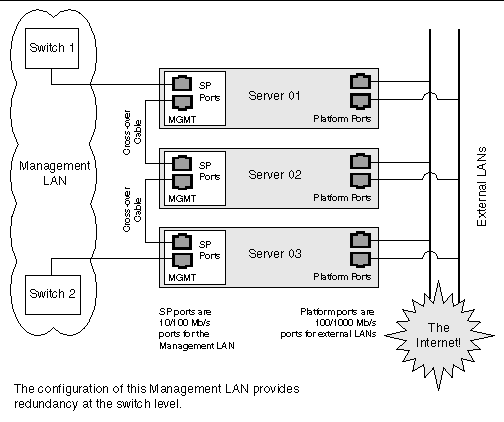
To interconnect the servers, you must use an RJ-45 cross-over cable. Cables can be connected to either the top or bottom SP port. To configure servers in a daisy chain, connect the first and last server in the chain to different switches.
In the configuration shown in FIGURE 1-10, two managed spanning-tree-capable switches are required to redundantly connect both the top and bottom of the chain. If the switches are not capable of spanning-tree discovery, then only connect either to the top or the bottom of the chain, but not both.
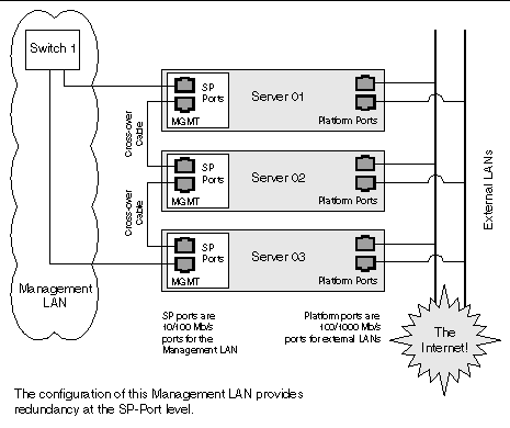
To interconnect the servers, you must use an RJ-45 cross-over cable. Cables can be connected to either the top or bottom SP port. To configure servers in a daisy chain, connect the first and last server in the chain to different switches.
In the configuration shown in FIGURE 1-11, a managed spanning-tree-capable switch is required to redundantly connect both the top and bottom of the chain. If the switch is not capable of spanning-tree discovery, then only connect either to the top or the bottom of the chain, but not both.
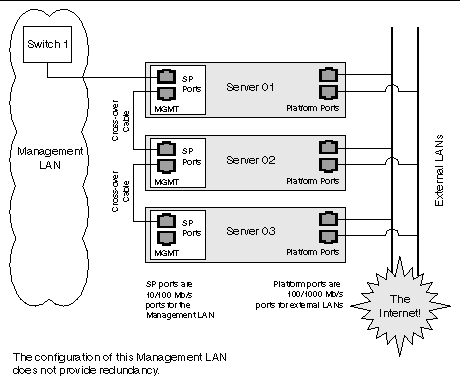
To interconnect the servers, you must use an RJ-45 cross-over cable. Cables can be connected to either the top or bottom SP port.
In the configuration shown in FIGURE 1-12, no redundancy is provided on the management LAN.
Follow these steps to power on and boot the server:
1. Perform this step to remove packaging inserts if you are powering on a Sun Fire V40z server the first time. Otherwise, skip to Step 2.
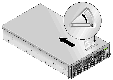
a. Loosen the captive screw on the cover latch, then rotate the latch toward the system rear to push back the cover (see FIGURE 1-13).
b. Lift the cover up and remove it.
c. Remove the plastic-foam packaging inserts from the PCI slot area near the back panel of the system.
|
Note - Do not remove the plastic air-baffle inserts from the PCI slots. |
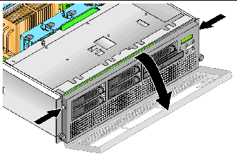
d. Remove the front bezel from the server by pressing in on the rubberized buttons on each side of the bezel, then swinging the bezel top downward (see FIGURE 1-14).
|
Note - The updated release (chassis PN 380-1206) of the server does not ship with the packaging insert in the CPU card slot. |
e. Open the CPU card door, which is located under the hard drive bays, to access the CPU card. Press down on the two buttons on the door and swing it downward so that it is open 180 degrees from the closed position (see FIGURE 1-15).
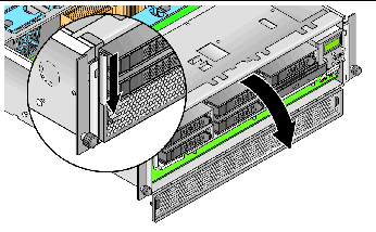
f. Remove the packaging insert from the CPU card slot.
g. Close the CPU card door and replace the front bezel onto the server.
h. Replace the cover onto the server and tighten the captive screw that secures the cover latch.
2. Ensure that a grounded AC power cord is plugged into all AC power connectors on the rear of the server and into AC power outlet(s). See FIGURE 1-8 or FIGURE 1-9 for the connector location.
3. Power on the server using one of the following two methods, depending on which server type you have:
a. Turn on the AC power switch on the server back panel (see FIGURE 1-8).
This switch provides AC power to the SP and basic hardware.
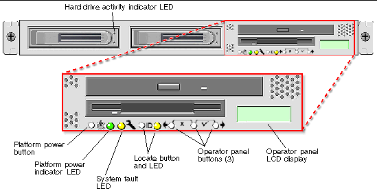
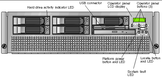
b. Push and release the platform power button on the server front panel (see FIGURE 1-16).
This button provides power to the BIOS, operating system and drivers.
This button provides power to the BIOS, operating system and drivers. There is no separate AC power switch on the Sun Fire V40z server; basic AC power was already applied when you plugged in a power cord to a power supply.
4. Continue with initial software setup tasks, as described in Chapter 2 of this guide.
Copyright © 2005, Sun Microsystems, Inc. All Rights Reserved.