| C H A P T E R 1 |
|
Introduction to the Sun Fire V20z and Sun Fire V40z Servers |
Strong server-management capabilities are crucial to maintaining mission-critical servers. Advance notification of problems and rapid diagnosis and correction are critical functions to an environment in which a few servers bear the bulk of the workload. The Sun Fire V20z and Sun Fire V40z servers and their extensive server-management capabilities lower costs by reducing failure and by potentially eliminating hands-on management.
This document describes how to perform remote management on the Sun Fire V20z and Sun Fire V40z servers.
The Sun Fire V20z server is an AMD Opteron processor-based, enterprise-class one rack unit (1U), two-processor (2P) server. The Sun Fire V40z server is also an AMD Opteron processor-based server, but it is a three rack unit (3U), four-processor (4P) server.
These servers include an embedded service processor (SP), flash memory, RAM, a separate Ethernet interface, and server-management software. They come equipped with superior server-management tools for greater control and minimum total cost of ownership. You can use the command-line interface (CLI), SNMP integration with third-party frameworks, or IPMI to configure and manage the platform with the SP. The dedicated SP provides complete operating-system independence and maximum availability of server management.
For the most up-to-date user documentation, for both the Sun Fire V20z and Sun Fire V40z servers, visit the following web site:
http://www.sun.com/products-n-solutions/hardware/docs/
Servers/Workgroup_Servers/Sun_Fire_V20z/index.html
To verify whether a document on the site is more recent than the document that you have, refer to the final two digits (the dash-roll) of the part number for that document or review the release date of the document.
|
Note - A document explaining the differences among the released versions of the Sun Fire V20z and Sun Fire V40z servers is also available at this web site. Refer to part number (PN) 817-7185. |
TABLE 1-1 defines the acronyms found in this document.
There are two options for remotely managing a Sun Fire V20z or Sun Fire V40z server:
The Sun Fire V20z and Sun Fire V40z servers include a dedicated chipset for complete operating-system independence and maximum availability of server-management functions. This chipset, called a service processor (SP), is an embedded PowerPC chip providing the following:
The SP runs an embedded version of Linux software, and all the server-management functions are developed as standard Linux applications. Its sole purpose is to support server management; therefore, the full functionality of the operating system is not available in the SP. Many familiar applications, such as FTP and Telnet, are not provided as they are not required to support the server-management feature set.
FIGURE 1-1 shows the back panel of the Sun Fire V20z server.
FIGURE 1-2 shows the back panel of the Sun Fire V40z server.
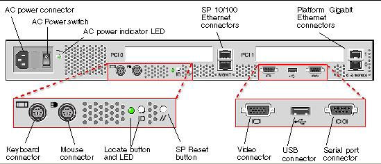
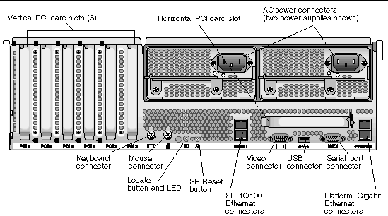
These servers include local and remote server-management capabilities through the SP; the SP supports four server-management interfaces:
Server-management capabilities are available from the command line.
See Appendix A for a list of server-management commands that you can use with these servers, as well as a description, the command format, a list of arguments, and a list of return codes for each command.
A system administrator can log in to the SP using Secure Shell (SSH) and issue commands, or more commonly, write a shell script that remotely invokes these operations.
The server-management commands enable you to efficiently manage each area of the server. From the command line, you can write data-driven scripts that automate the configuration of multiple machines. For example, a central management system can cause many servers to power on and boot at a specified time, or when a specific condition occurs.
For more information about scripting, see Further Management Information.
Simple Network Management Protocol (SNMP) management provides remote access by SNMP-compliant entities to monitor the health and status of the server. The SP sends SNMP alerts to external management functions when warranted.
For more information about SNMP, refer to SNMP Server Management.
The diagram in FIGURE 1-3 illustrates the communication paths for the different server-management options.
You can use the operator panel to configure network settings for the SP. See FIGURE 1-4 or FIGURE 1-5 for the operator panel location on your server.
|
Note - The SP defaults to Dynamic Host Configuration Protocol (DHCP) networking if the operator panel is not interactively engaged on the first power-up. |
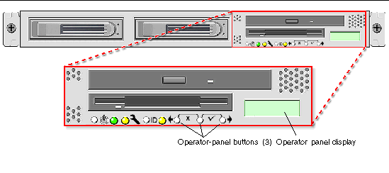
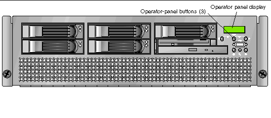
The operator panel displays information on the operator panel display in two lines; you respond to prompts or initiate actions using the following buttons.
For a complete list of the menu options on the operator panel, refer to "Operator Panel" in Chapter 1 in the Sun Fire V20z and Sun Fire V40z Servers--User Guide.
Administrators can define several different user groups, or types, on the server. Capabilities of the different user types are defined in TABLE 1-3.
For example, when you log in to the system the first time using the setup account, you must set up the initial manager account so that other user accounts can be managed. (See Creating the Initial Manager Account for details.)
|
All capabilities except user-account management and SP field upgrades |
|
There are two classes of SP users: one class of users can log in to the SP through SSH; the other class of users can establish IPMI sessions to the SP.
These two classes of users are managed independently:
It is possible to configure the SP so that directory-services (ADS/NFS) users can log in to the SP through SSH. However, these directory-services users cannot log in to the SP through the IPMI.
Passwords for local, non-IPMI users are stored in a standard Linux shadow-password file, which enhances the security of the system. The hashed passwords are in a file that is not readable by users.
Passwords for IPMI users are stored separately. The IPMI password file is not readable by users, but passwords are stored unencrypted because of limitations imposed by the IPMI authentication algorithms.
To accomplish most systems management tasks, you can use any of the systems management tools that are included with your server. TABLE 1-4 lists some common systems management tasks and the tools that you can use to accomplish each task. For information about the systems management commands, see the appendixes in this guide. Commands documented in the online help are noted in the table. For information about running diagnostic tests, see the Sun Fire V20z and Sun Fire V40z Servers--Troubleshooting Techniques and Diagnostics Guide.
This procedure describes the steps for the initial setup of the SP.
This section contains two alternative methods you can use to define SP network settings:
|
Note - As an alternative, if no DHCP server or physical access is available, you can configure the SP using IPMItool in conjunction with an IPMI kernel driver. To configure your server for IPMI, perform the correct procedures for your operating system in Task III: Enabling IPMI Access on the Server, then Task IV: Enabling IPMI LAN Access. |
The following procedure describes how to configure the SP network settings using DHCP from the operator panel. If your network does not use DHCP, or you want to assign a static IP address to the SP, follow the instructions in Assigning Static SP Network Settings.
1. Press any operator-panel button on the server front panel (see FIGURE 1-6).
The operator panel displays the first menu option:

2. Press the Forward button until you reach the SP menu.
3. Press the Select button to display the SP menu options.
The following prompt appears with the default response:
5. Press the Forward button to change to Yes, then press the Select button.
6. Press the Select button at the confirmation prompt.
The server attempts to contact a DHCP server for an IP address. When the server receives a DHCP response, the operator panel displays the DHCP-assigned SP IP address. The SP IP address is configured and the server is ready for use.
|
Note - Depending on your network conditions, it may take five to ten seconds for the new IP address allocated by the DHCP server to appear in the operator panel. |
|
Note - A prompt appears that asks whether you want to perform autoconfiguration. As an alternative to configuring an SP manually, you can run autoconfiguration, which replicates the configuration of one SP to another. Refer to Autoconfiguring the SP for instructions on autoconfiguration. |
7. Continue with Task II: Securing the SP for instructions on creating the initial manager account.
From the operator panel, follow these steps to configure the SP network settings using a static IP address. You must specify a subnet mask and default gateway. This example uses the following sample settings:
IP Address: 10.10.30.5
Subnet Mask: 255.255.255.0
Default Gateway: 10.10.30.254
1. Press any operator-panel button on the server front panel (see FIGURE 1-6).
The operator panel displays the first menu option:
2. Press the Forward operator-panel button until you reach the SP menu.
3. Press the Select operator-panel button to display the SP menu options.
4. Press the Select operator-panel button.
The following prompt is displayed with the default response:
5. Press the Select operator-panel button.
The operator panel displays the following:
6. With the cursor in the first field, increase or decrease the value using the Back or Forward operator-panel button.
This field can hold a value between 0 and 255.
7. After reaching your desired value, press the Select operator-panel button to advance the cursor to the next field.
8. Repeat Step 6 and Step 7 for each field until the desired IP address is displayed, then use the Enter button combination to save the IP Address.
The process continues to the next network setting, the subnet mask. The operator panel displays the following:
9. Edit the subnet mask setting in the same manner as you did for the IP address. When finished, use the Enter button combination to save the subnet mask.
The process continues to the next network setting, the default gateway. The operator panel displays the following:
10. Edit the default gateway setting in the same manner as you did for the IP address and the subnet mask. When finished, use the Enter button combination to save the default gateway.
The operator panel displays the following confirmation prompt:
11. Press the Select operator-panel button to use the new data, or use the Cancel button combination to disregard the new information.
The SP address is now configured and the server is ready for use.
|
Note - A prompt appears that asks whether you want to perform autoconfiguration. As an alternative to configuring an SP manually, you can run autoconfiguration, which replicates the configuration of one SP to another. Refer to Autoconfiguring the SP for instructions on autoconfiguration. |
12. Continue with Task II: Securing the SP.
After you install the server and configure the SP's network settings, you must create the initial manager account. You can then perform initial configuration of the server and create additional user accounts. Only the administrator who does the initial system configuration can create the initial manager account.
A setup account is included with each server. This setup account has no password. When you log in to the SP the first time using the setup account, you are prompted to define the initial manager account with a password and an optional public key.
User names and passwords are strings that consist of any alphanumeric character, underscore, hyphen, or period.
There are two methods you can use to create the initial manager account:
Log in to the setup account and create the initial manager account by following this procedure:
1. Using an SSHv1 or SSHv2 client, connect to the IP address of the SP.
2. Authenticate as the user setup with no password required.
3. Follow the on-screen prompts to create the initial manager account.
After you create the initial manager account, the setup account is deleted and you are logged out of the server. You can then log in using the new initial manager account, from which you can create other user accounts.
For information about the SM Console features, see Systems Management Console Features.
To create the first manager account from the SM Console:
1. Type the SP name or IP address as the URL or address in a browser, to enter the SM Console.
The main SM Console screen appears.
|
Note - When you create the initial manager account, you are prompted to accept a license agreement. After you create the initial manager account, this prompt no longer appears. |
2. At the Create Initial Manager-Level User ID screen, type a user name for this account.
3. Type a password for the account.
4. Re-enter the password to confirm the password.
5. Click the checkmark button.
6. Use the SM Console to select initial configuration options.
After you create the initial manager-level user, the Initial Configuration Checklist screen is displayed in the SM Console. This screen enables you to determine the options you want for the initial setup of the SP.
The Initial Configuration Checklist is a table that lists the SM Console menu options and the commands you use to configure each option. It also includes links to the online help that provides instructions for each option.
|
Note - The IP address, user name, and password that you configure are referred to in subsequent examples as the spipaddr, spuser, and sppasswd. |
This section contains two alternative procedures: one for a Linux software-based server and one for a Solaris x86-based server. Use the procedure that corresponds to your OS:
1. Log in to the server and authenticate as the root user.
2. Install the custom OpenIPMI Linux kernel driver from the Sun Fire V20z and Sun Fire V40z Servers Documentation and Support Files CD.
The drivers are located in the CD directory /support/sysmgmt/.
Browse to the OS variant installed on your server. The options are:
3. Ensure that the kernel-source RPM is already installed on your distribution by running the command:
# rpm -qvi kernel-source
If this utility reports that the kernel-source software package is not installed, install the kernel-source RPM that is current for your installed Linux distribution.
# rpm -ivh /tmp/kernel-source*.rpm
4. Install the OpenIPMI Linux kernel driver RPM.
a. Browse to the OS variant installed on your server. The options are:
b. Install the OpenIPMI RPM file by running the command:
|
Note - The kernel driver will be compiled using the kernel-source code during installation. |
IPMItool is the command-line interface (CLI) server-management client.
# rpm -ivh ipmitool*.x86_64.rpm
6. Test the IPMI kernel device driver and client application by running the following command:
# ipmitool -I open chassis status
Successful output looks similar to the following:
"
System Power: on
Power Overload: false
Power Interlock: inactive
Main Power Fault: false
Power Control Fault: false
Power Restore Policy: unknown
Last Power Event:
Chassis Intrusion: inactive
Front-Panel Lockout: inactive
Drive Fault: false
Cooling/Fan Fault: false
"
|
Note - On a subsequent reboot, the IPMI kernel driver might have to be loaded with the following command:
|
|
Note - If you upgrade your Linux kernel, refer to Upgrading the Linux Kernel. |
1. Log in to the server and authenticate as the root user.
2. Run the following command to install the LIPMI Solaris x86 kernel driver and the IPMItool management control application.
These files are located on the Documentation and Support Files CD in the /support/sysmgmt/solaris9 directory.
Confirm installation of all packages when prompted.
This section contains three alternative procedures: two in-band procedures and one out-of-band procedure. Use the procedure that corresponds to your OS:
1. If the server is powered off, boot the local OS.
2. Log in to the server and authenticate as the root user.
3. Load the OpenIPMI kernel device driver (as installed in Step 3 of Enabling IPMI Access on a Linux-Based Server (In-Band)).
# modprobe ipmi_kcs_drv
4. Using the following commands in IPMItool, configure the network settings for the SP.
|
Note - For more information about the syntax for IPMItool commands, refer to Syntax. |
# ipmitool -I open lan set 6 ipaddr ipaddr # ipmitool -I open lan set 6 netmask netmask # ipmitool -I open lan set 6 defgw ipaddr gwipaddr # ipmitool -I open lan set 6 password ipmipasswd
1. If the server is powered off, boot the local OS.
2. Log in to the server and authenticate as the root user.
3. Using IPMItool, configure the network setting for the SP by using the following commands.
|
Note - For more information about the syntax for IPMItool commands, refer to Syntax. |
# ipmitool -I lipmi lan set 6 ipaddr ipaddr # ipmitool -I lipmi lan set 6 netmask netmask # ipmitool -I lipmi lan set 6 defgw ipaddr gwipaddr # ipmitool -I lipmi lan set 6 password ipmipasswd
1. Using an SSHv1 client or SSHv2 client, log in to the IP address of the SP.
2. Authenticate as the newly created manager user (see Task II: Securing the SP").
# ssh spipaddr -l spuser
3. Enable IPMI LAN access and assign a password when prompted.
# ipmi enable channel lan # exit
|
Note - This password will be referred to as ipmipasswd in subsequent examples. |
4. Using IPMItool, test the IPMI LAN access.
# ipmitool -I lan -H spipaddr -P ipmipasswd chassis status
Upgrading the installed Linux kernel to a newer version requires you to recompile the upgraded IPMI kernel device driver.
1. Install the kernel-source RPM that matches the version of the upgraded kernel binary RPM package.
2. Log in to the server and authenticate as the root user.
3. Change to the following directory.
# cd /usr/src/kernel-modules/openipmi
4. Recompile the module by running the following commands.
# make clean # make # make install
5. Re-test the IPMI kernel device driver and client application by running the following command.
# ipmitool -I open chassis status
Successful output should look similar to the following:
"
System Power: on
Power Overload: false
Power Interlock: inactive
Main Power Fault: false
Power Control Fault: false
Power Restore Policy: unknown
Last Power Event:
Chassis Intrusion: inactive
Front-Panel Lockout: inactive
Drive Fault: false
Cooling/Fan Fault: false
"
|
Note - On a subsequent reboot, the IPMI kernel driver might have to be loaded with the following command:
|
When deploying your server, ensure that you determine the best integration strategy for your environment.
The Sun Fire V20z and Sun Fire V40z servers include network connections for the SP that are separate from network connections for the platform. This enables you to configure the server so that the SP is connected to an isolated, management network and is not accessible from the production network.
You can interconnect multiple servers in different daisy-chain configurations by using the SP connectors to form a management LAN, as shown in FIGURE 1-7, FIGURE 1-8, and FIGURE 1-9. The figures also show how the servers are connected to external LANs using the platform Gigabit Ethernet connectors.
|
Note - It is a best practice to use cross-over cables of at least one meter in length for daisy-chaining the servers. |
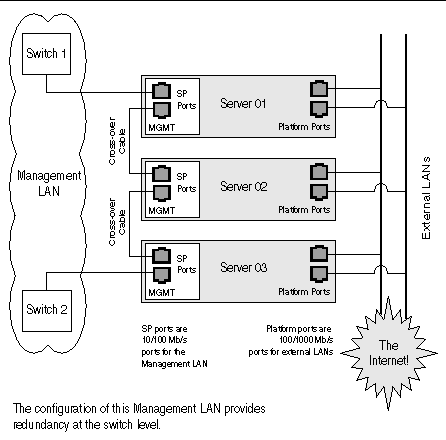
To interconnect the servers, you must use an RJ-45 cross-over cable. Cables can be connected to either the top or bottom SP port. To configure servers in a daisy chain, connect the first and last server in the chain to different switches.
In the configuration shown in FIGURE 1-7, two managed switches that are capable of spanning-tree discovery are required to redundantly connect both the top and bottom of the chain. If the switches are not capable of spanning-tree discovery, then only connect either to the top or the bottom of the chain, but not both.
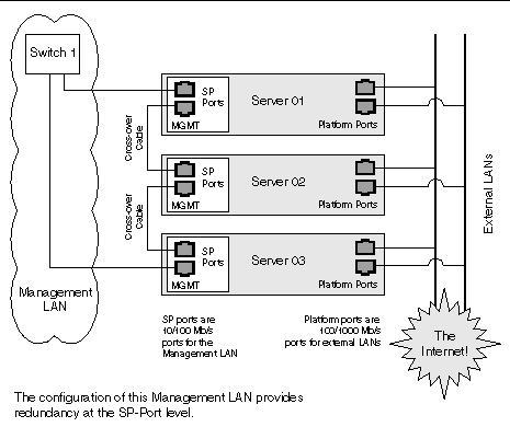
To interconnect the servers, you must use an RJ-45 cross-over cable. Cables can be connected to either the top or bottom SP port. To configure servers in a daisy chain, connect the first and last server in the chain to different switches.
In the configuration shown in FIGURE 1-8, a managed switch that is capable of spanning-tree discovery is required to redundantly connect both the top and bottom of the chain. If the switch is not capable of spanning-tree discovery, then only connect either to the top or the bottom of the chain, but not both.
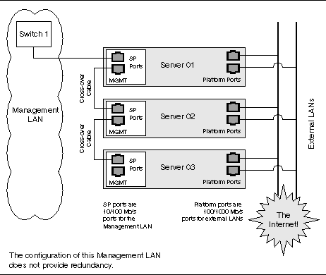
To interconnect the servers, you must use an RJ-45 cross-over cable. Cables can be connected to either the top or bottom SP port.
In the configuration shown in FIGURE 1-9, no redundancy is provided on the Management LAN.
Installation of the platform drivers and applications provides the following capabilities:
If you do not install the platform software, the following features will not be available from the SP:
The features or characteristics below are available without installation of the platform drivers. However, they require that the SP was fully booted during the last BIOS boot:
Also note these other important points about platform software:
|
Note - For complete information about the menu options available through the operator panel, refer to the Sun Fire V20z and Sun Fire V40z Servers--User Guide. |
If you attempt to update the SP software using the operator panel when the IP address for the SP has not been set, the update fails. Ensure that the IP address has been set prior to attempting an update. For more information, refer to the Sun Fire V20z and Sun Fire V40z Servers--Installation Guide.
A new network share volume (NSV) that is installed on your network contains firmware packages. You can make these firmware packages available to a SP in either of these ways:
 application that transfers the packages from the NSV to the SP.
|
Note - The latest BIOS version number is never the same as the latest NSV version number, as represented in the configuration file example data lines in Configuring and Starting the Update Server Application. |
In the illustration above, the NSV has been unzipped and saved to a server that is network-accessible by the SPs that require updated packages. SP1 has mounted the NSV directly. SP2, SP3, and SP4 access the NSV through the Update Server.
|
Note - In this example, SP1 cannot update the SP base package without using the Update Server application. |
Select a server that is network-accessible to the SP(s).
To install the NSV, follow the steps below.
1. Download the latest version of the NSV from http://www.sun.com/servers/entry/v20z/downloads.html.
2. Extract files from the compressed NSV to a location on your selected file server.
|
Note - When you unzip a compressed file on Linux, use the -a switch (for example, unzip -a filename.zip) to force text files to convert to the target operating system's appropriate end-of-line termination.
|
3. For Linux-based systems, ensure that the NSV directory has been exported.
4. Decide whether you will update by using the Update Server application or by using an NFS mount:
For example, if the IP address of the machine with the new NSV is 10.10.20.100 and you extracted the NSV files to a directory named newNSV, you would run the command:
sp add mount -r 10.10.20.100:/newNSV -l /mnt
The NSV will then be available to the SP at /mnt/sw_images/.
Continue with Identifying Packages for Update.
The Update Server configuration file enables you to export multiple packages with multiple versions to one or more SPs. To select the appropriate updates, follow the instructions below.
1. Navigate to NVS/update_server/Vx.xx (where Vx.xx is the version you want) to find the configuration file.
The configuration file includes example data lines, shown below.
|
Note - The latest BIOS version number is never the same as the latest NSV version number, as seen in the example above. |
Each data line contains three space-delimited values:
In order to support BIOS updates for several products that each require unique BIOS firmware, the BIOS package must include the product ID. The product ID is the value that is returned by the platform get product-id command. It is also found in the BIOS software manifest (swinventory.xml) that is included in an NSV. The actual product ID used in the example above is x250 Alpha. When you include this in the BIOS package type in the configuration file, you must add the hyphen between BIOS and the product ID, and you must remove all spaces from the product ID string.
2. In the configuration file, each data line is preceded by a # sign. To indicate a file that should be updated, add the correct version number and remove the # sign at the beginning of the data lines.
3. Navigate to the NSV folder that contains the Update Server application and start the server via the command line:
java -jar updateServer.jar -c updateServer.config -p <port> -l logfile.log
The updateServer.jar file is located in the update_server folder of the NSV.
1. To determine which packages currently are installed on an SP, run this command from the SP:
2. To determine which packages are available from a running Update Server application, run this command from the SP:
inventory get remote-software -i <server_ipaddress> -p <server_port>
|
Note - Some older versions of the SP do not accept the -i or -p options. These older versions accept only these arguments: [{-a|--all}], [{-D|--Delim}], and [{-H|--noheader}]. |
3. To compare currently installed packages with packages that are available on a mounted NSV, run this command from the SP:
inventory compare versions -f <manifest_filename>
4. To compare currently installed packages with packages that are available on a running Update Server, run this command from the SP:
inventory compare versions -i <server_ipaddress> -p <server_port>
|
Note - Some older versions of the SP do not accept the -i or -p options. These older versions accept only these arguments: [{-a|--all}], [{-D|--Delim}], and [{-H|--noheader}]. |
|
Note - You can use the Update Server application to install this package, or you can use the SP Update Flash option in the operator panel's SP menu. |
The SP base component includes the SP Value-Add component, so it also is updated as part of this process.
|
Note - Because the Value-Add package can contain all feature updates in a new release, check the Sun Fire V20z and Sun Fire V40z Servers--Release Notes to determine which package you should update. |
2. Execute the SP command to start the update process on the SP:
sp update flash all -i <server_ipaddress> -p <server_port> -r <version>
3. Monitor the update process on the server.
Messages are displayed as the installation process begins and ends. (More details of the update processes are in the Update Server log file.) When the update is complete, the SP reboots with the new version.
The SP Value-Add component can contain all the new features in a new release. Check the Sun Fire V20z and Sun Fire V40z Servers--Release Notes to determine whether to update the Value-Add package or the SP Base package.
|
Note - You do not have to perform this upgrade if you already updated the SP Base package. |
sp update flash applications -i <server_ipaddress> -p <server_port>
-r <package_version>
|
Note - If you use an NFS mount, execute this command:
|
There are three methods available for updating the BIOS, as shown in the procedures in this section:
1. Follow the steps in Configuring and Starting the Update Server Application to use the Update Server application.
2. At the SP prompt, type this command:
platform set os state update-bios -i <server_ipaddress> -p <server_port> -r <package_version>
1. Log in to the SP and mount the NSV.
For example, if the IP address of the machine with the new NSV is 10.10.20.100 and you extracted the NSV files to a directory named newNSV, you would run the command:
sp add mount -r 10.10.20.100:/newNSV
The NSV will then be available to the SP at /mnt/sw_images/.
2. At the SP prompt, type this command:
platform set os state update-bios /mnt/sw_images/platform/firmware/bios/Vx.x.x.x/bios.sp
Where Vx.x.x.x is the version number you want.
1. Copy the BIOS image directly from the NSV to the /tmp folder on the SP file system.
2. At the SP prompt, type this command:
platform set os state update-bios /tmp/bios.sp
The SP-based diagnostics tests are stored in the NSV and are referenced by the /diags symbolic link in the SP. The SP software references a default version of the diagnostics. However, if a new version is released and stored on the NSV, you must point to that new version in order to use it.
2. Mount the NSV, using the sp add mount command. For example:
sp add mount -r <network_path>
This mounts the directory specified by network_path on /mnt.
3. To verify that the mount was successful, type ls /mnt/diags. For example:
4. Use the sp update diags command to establish a soft link from /diags to the desired diagnostics directory. For example:
sp update diags -p /mnt/diags/V2.4.1.0
5. To verify the new soft link, type ls -l /diags. For example.
ls -l /diags /diags -> /mnt/diags/V2.4.1.0
6. To verify that the diagnostics subsystem is available, type this command:
The output lists all the subcommands of the diags command.
|
Note - See the Sun Fire V20z and Sun Fire V40z Servers--User Guide for a complete list of diagnostics modules and sample output. |
You can also use the autoconfiguration option to update the SP. Autoconfiguration replicates the majority of configuration files from an SP that has already been configured to another SP, so that the two servers have identical configurations, except for the host name and IP address.
For example, after you configure a single SP (set up users, hosts, certificates, mounts and so on), you then run autoconfiguration on each additional SP so that the settings are identical. In addition, if you modify the configuration of one SP, you can update all of them by re-running autoconfiguration on each one. (For this reason, set the IP address of the autoconfigure server to x.x.x.1.)
For a list of files that are copied or not copied during the autoconfiguration process, see Files Copied During the Autoconfiguration Process.
Autoconfiguration has these limitations:
You can start autoconfiguration either when you are prompted at the completion of setting the IP address of the SP, or by selecting Autoconfigure from the SP menu option on the operator panel at any time.
To perform autoconfiguration of an SP, follow these steps.
1. On the operator panel, press the Forward or Back button until the following prompt appears.
3. Press the Forward or Back button to change the prompt to Yes.
For instructions on setting an IP address, refer to the Sun Fire V20z and Sun Fire V40z--Server Installation Guide.
The SP attempts to locate an IP address.
Where x.x.x is the first three octets of the SP IP address. For example, if the address is 10.10.30.19, the address that displays in the prompt appears as 10.10.30.1.
In this case, press the Select button on the operator panel to start the autoconfiguration.
In this case, you must manually enter an IP address before you press the Select button on the operator panel to start the autoconfiguration.
5. Wait until the autoconfiguration is complete, at which point the SP automatically reboots.
The following message is displayed when the autoconfiguration is running:
|
Note - If the autoconfiguration is unsuccessful, a failure message displays. Press any button on the operator panel to clear it. |
TABLE 1-5 provides the list of files copied during the autoconfiguration process. TABLE 1-6 provides the list of files that are not copied during the process.
The autoconfiguration process performs some safety checks on some files.
All files are transferred between the two hosts through an SSL socket connection. This is true even if the option ssl_not_enforced is enabled.
Use the following commands if you need to determine the MAC address of your server's SP or platform:
# ssh spipaddress -l spusername sp get mac
# ssh spipaddress -l spusername platform get mac
You can manage the servers by using line commands or by using the web-based Systems Management (SM) Console graphical interface. This section gives an overview of the actions you can do with the SM Console interface.
|
Note - For full information on the line commands, see the appendixes in this guide. |
Admin-level and manager-level users can use the SM Console to configure the SP network settings to define the IP address method (static or DHCP), and other network settings such as the host name, DNS server address, and domains.
|
Note - As discussed in the previous section, you also can configure network settings from the operator panel, or you can use the sp ip commands, which are explained in the online help. |
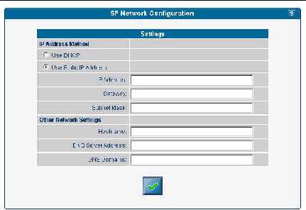
To configure the SP network settings from the SM Console:
1. Click Configuration>SP Network from the menu bar.
2. In the Settings table, select which IP Address Method (DHCP or Static IP Address) that you want to use.
3. If you choose Static IP Address, type the IP address, gateway address, and subnet mask.
4. Identify other network settings.
5. Click the checkmark button to save the settings.
|
Note - If you choose DHCP, the SP broadcasts for a DHCP server to obtain a dynamic IP. The IP address information is displayed, but you cannot edit it. |
Admin-level and manager-level users can start and stop the platform operating system from the SM Console. Choose Management>Platform Operations from the menu bar, then choose one of the options listed in the table below.
After you choose an option and click the checkmark button, the operation is initiated on the server. The help text displays any processing and results messages. The current state (normal, warning, or critical) is reflected in the System Status button, so you can monitor the progress.
When you move the cursor over the Platform Operating System button, one of these states is displayed in the help panel:
|
Note - You can perform platform state management from the command line with the platform subcommands. See Appendix F for more information.
|
Admin-level and manager-level users can configure the system to:
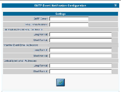
SMTP notification ensures rapid notification about events and rapid response to critical situations. You can use the SM Console or the sp smtp commands to configure SMTP event notification.
Follow these steps to configure automatic SMTP email alerts from the SM Console.
1. Click Configuration>SMTP Event Notification from the menu bar.
2. Type the SMTP server name (either the host name or IP address of the SMTP server where you want email to be routed). Use an IP address unless DNS is configured on the SP.
3. For each level of severity, type a comma-separated list of email addresses.
These are the addresses that will receive email for each level of severity. Severity levels are:
|
Note - Type separate address lists for short and for long email formats. Type a comma between each email address. Type a separate list for pager email addresses that require shorter text. |
4. Click the checkmark button to save the settings.
Configure the directory services options to define how SP user name and password information is stored or accessed.
You can use the SM Console or the access subcommands to configure the directory services options. See Appendix B for more information.
To configure directory services from the SM Console:
1. Click Access Control>Directory Services from the menu bar.
Select the type of directory service you want to use:
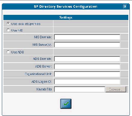
2. Type the domain name for the option you selected in Step n.
3. Type the server name for the option you selected in Step n. (For multiple servers, type a comma between each server name.)
4. If you chose ADS, also type the organizational unit, ADS Logon ID, and the location of the keytab file.
See Creating Keytab Files for ADS.
5. Click the checkmark button to save the settings.
Remote users who are authenticated via directory services have access to the SP only via a group mapping that maps the user's remote group to an SP administrative group.
To simplify configuration on the SP, manager-level users can map directory service groups to predefined groups. When you map those users (members of directory services groups) to an SP administrative group, they automatically have appropriate access rights.
The Directory Service Group Mappings table identifies existing group mappings. This table also provides options for mapping other directory service groups to an SP group. For example, if Directory Services group 5 is mapped to manager, all members of group 5 are granted manager-level privileges on the SP.
To map directory service groups from the SM Console:
1. Click Access Control>DS Group Mappings from the menu bar.
The current group mappings table is displayed. Directory service groups are listed alphabetically.
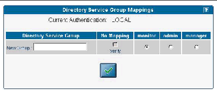
2. Choose one of the following:
3. Click the check mark button.
To use Active Directory Service (ADS) as a directory service on the SP, you must create an active directory account. The name service library on the SP uses this account to authenticate itself to the LDAP interface of the active directory server.
ktpass -princ <logon>@<domain> -pass <password> -mapuser <logon> -out <output filename>
Admin-level and manager-level users can configure the date and time setting for the SP clock. Use the sp date command from the command line or configure date and time from the SM Console.
If you configure the SP before you load the platform operating system and you want to set the time to synchronize with ADS and other network services, follow the procedure below.
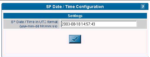
1. Click Configuration>SP Date/Time from the menu bar.
2. Identify the date and time on the SP clock.
The current SP time displays in yyyy:mm:dd hh:mm:ss format. FIGURE 1-15 illustrates an example of this format.
3. Click the checkmark button to save the settings.
Set up web access to the SP with either an encrypted or a non-encrypted communication method.
By default, all messages between your browser and the SP are encrypted according to Hypertext Transfer Protocol over Secure Sockets Layer (HTTPS). Version 0.9.6j is supported.
1. Allow browsers to communicate with the SP via non-encrypted messages by one of the following two methods:
With SSL disabled, HTTP requests are serviced directly without any redirection to HTTPS. HTTPS requests continue to be secure.
|
Note - If you enable the HTTPS protocol, your browser will display a warning message that states that it cannot verify the validity of the Server Certificate. This warning is informational and you can ignore it safely. To upload a certificate that is signed by your own organization or by an independent certificate authority, select User Supplied, as described in Configuring the SSL Certificate From the SM Console. |
2. To revert to the default behavior, type this command:
With SSL enabled, HTTP requests are redirected automatically to equivalent HTTPS requests to maintain site security.
Admin-level and manager-level users can enable or disable SSL encryption and can define the SSL certificate that is used to manage transmission security.
|
Note - You also can use sp ssl commands to configure the SSL certificate. See Appendix H or the SM Console online help for details about commands. |
Follow these steps to configure the SSL certificate from the SM Console:
1. Click Configuration>SSL Certificate from the menu bar.
2. Select Required or Optional to designate SSL access.
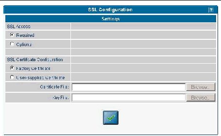
3. Do one of the following, depending on whether you selected Required or Optional:
a. Type the name of your generated certificate file to be installed with Apache on the SP, or click the Browse button to search for a file.
b. Type the name of your generated key file to be installed with Apache on the SP, or click the Browse button to search for a file.
4. Click the checkmark button.
The System Status window displays an image that represents the physical layout and status of all hardware components and sensors. You can use this window to identify components that have problems, or failed components that must be replaced. To access this window, click the System Status button from the toolbar in the SM Console.
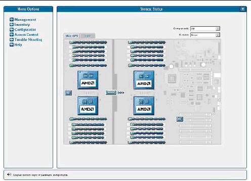
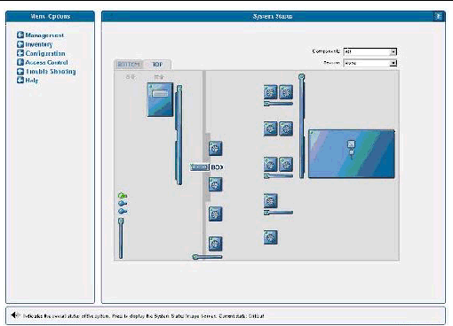
The component images represent the actual physical hardware components including their approximate location, size, and status. The hardware layout for the Sun Fire V40z server is represented in two layers. (FIGURE 1-17 illustrates the default, bottom tab view for the dual-core Sun Fire V40z server.) Click the Bottom and Top tabs at the top of the image to change views.
You also can display component details for troubleshooting purposes. To view details about a component, click on the image of that component. You also can use the pulldown menus in the top right corner of the window to locate specific component types (CD-ROM drives, CPUs, disk drives, fans, and so on) and specific sensor types (fan, power, and temperature sensors).
Sensor images represent the approximate location, current value, and warning or critical thresholds of system sensors. Current information about the sensor (name, type, current value, low and high warning, critical thresholds, and status) is displayed in a gauge component in the top right corner of the image.
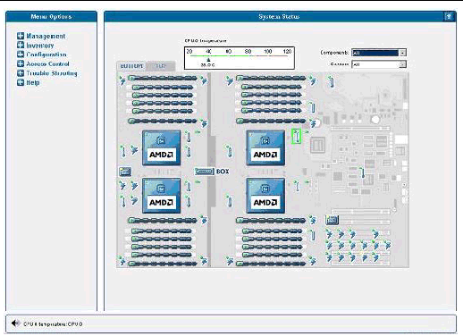
To view values for a sensor, click on the image of the sensor. In FIGURE 1-19, which illustrates the bottom layer, the temperature sensor gauge for CPU 0 is displayed.
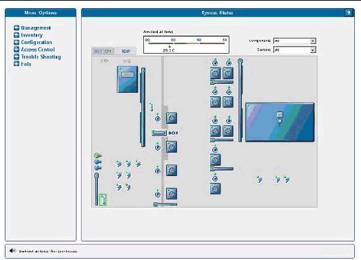
In FIGURE 1-20, which illustrates the top layer, the sensor gauge for the ambient air temperature is displayed.
|
Note - See the SM Console online help for additional instructions and details about management tasks. |
Administrators with appropriate privileges can use the SM Console's System Events table to view detailed information about all active events. They also can perform various actions that are related to each event.
Each active event is displayed on its own row in the table, as illustrated in FIGURE 1-21.
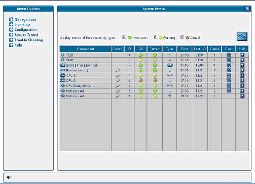
TABLE 1-9 describes the columns in the System Events table.
|
The unique name of the component that has caused this event. Components can be hardware or software. |
|
|
Contains a unique event ID for each event enabling you to track the event in your external trouble-ticket system and query the log files for all actions related to the event. |
|
|
Displays the highest severity that this event has ever achieved: informational (green), warning (yellow), and critical (red) icons. Click the icon to view details for the event. |
|
|
Displays the current severity: informational (green), warning (yellow), and critical (red) icons. Also displays a descriptive message. These descriptions might be lengthy, (for example, describing the nominal, warning, critical, and current temperature for a fan) and therefore are displayed in the help panel. |
|
|
Identifies the event type. Refer to TABLE 1-10 for a description of the icons representing each type. |
|
|
Lists the date and time at which the event was initially generated. Only the time is displayed in the table; help text at the bottom of the window displays the entire date and time. |
|
|
The date and time at which the event was most recently generated. Only the time is displayed in the table; help text at the bottom of the window displays the entire date and time. |
|
|
Lists the number of times the event has occurred. If a new event has the same component and event type as a current, uncleared event, a new event is not created but the count for the current event is incremented and the current severity is updated in the Current column. |
|
|
Clicking this button clears the event. You must manually clear all events. A cleared event is deleted from the server and automatically cleared from any other connected SM Console System Events screen. Only admin-level and manager-level users can clear events. |
|
|
Note - You also can use the sp get events command to obtain information about events. See Appendix H or the online help for more information. |
The SM Console displays the icons that are illustrated in TABLE 1-10 to represent specific types of events.
|
|
|
|
|
|
|
|
|
|
|
|
|
|
|
|
|
|
|
|
|
|
|
|
|
|
|
Note - See the Sun Fire V20z and Sun Fire V40z Servers--Troubleshooting Techniques and Diagnostics Guide for a table of system events and troubleshooting suggestions. |
Copyright © 2004-2007, Sun Microsystems, Inc. All Rights Reserved.