| Sun Fire X4140, X4240 and X4440 Servers Installation Guide |
| C H A P T E R 2 |
|
Installing the Server in a Rack |
This chapter describes how to install a Sun Fire X4140, X4240, or X4440 server into a rack using the rail assembly in the rackmount kit.
| Note - If your rackmount kit came with its own instructions, use the instructions in your rackmount kit instead of the instructions in this chapter. After performing the installation, proceed to Chapter 5 to configure the service processor. |
This chapter includes the following topics:
| Note - In this guide, the term rack means either an open rack or a closed cabinet. |
To install your server into a four-post rack using the slide rail and cable management arm (CMA) options, perform the following tasks in the order shown:
3. Installing the Mounting Brackets Onto the Server
4. Installing the Cable Management Arm
5. Verifying Operation of the Slide Rails and CMA
6. Connecting Cables to the Sun Fire X4140 Server
The rack kits come in two varieties; toolless, or express rail kits, and bolt-on rail kits.
Check that your rack is compatible with the slide rail and cable management arm (CMA) options. The optional slide rails are compatible with a wide range of equipment racks that meet the following standards:
On some slide rail kits, the mounting bracket is shipped inside of the slide rail. If the mounting bracket is already separate from the slide rail, skip this procedure.
To separate the mounting brackets from the slide rail:
2. Locate the slide-rail lock at the front of one of the slide-rail assemblies, as shown in FIGURE 2-1.
3. Squeeze and hold the tabs at the top and bottom of the lock while you pull the mounting bracket out of the slide-rail assembly until it reaches the stop.
4. Push the mounting bracket release button toward the front of the mounting bracket, as shown in FIGURE 2-1, and simultaneously withdraw the mounting bracket from the slide-rail assembly.
5. Repeat for the remaining slide-rail assembly.
FIGURE 2-1 Disassembling the Slide Rail Before Installation

To install the mounting brackets onto the sides of the server:
1. Position a mounting bracket against the chassis so that the slide-rail lock is at the server front, and the keyed openings on the mounting bracket are aligned with the locating pins on the side of the chassis.
FIGURE 2-2 Aligning the Mounting Bracket With the Server Chassis
(Sun Fire X4140 Server Shown)

2. Fasten the mounting bracket to the server:
a. Align the heads of the locating pins with the keyed openings in the mounting bracket. See FIGURE 2-2.
b. Place the mounting bracket on the pins so that it is flush with the side of the server, and the locating pins protrude through the holes on the mounting bracket.
c. Slide the mounting bracket towards the front of the chassis until the bracket clip locks into place with an audible click.
3. Verify that the rear locating pin is securely fastened to the server. (See FIGURE 2-2.)
4. Repeat Step 1 through Step 3 to install the remaining mounting bracket on the other side of the server.
To attach toolless slide-rail assemblies to the rack:
1. Position a slide-rail assembly in your rack so that the brackets at each end of the slide-rail assembly are on the outside of the front and rear rack posts. (See FIGURE 2-3.)
2. Push the slide-rail assembly against the rack.
The toolless brackets latch to the rack post with an audible click.
To attach bolt-on slide-rail assemblies to the rack:
1. Select hardware to match your rack posts from the bag of connectors that came with the slide rail kit.
If you use the caged nuts, press them into the holes from the outside of the rack until they clip into place. Once the caged nuts are in place, they provide threaded mounting holes.
2. Position a slide-rail assembly in your rack so that the brackets at each end of the slide-rail assembly are on the outside of the front and rear rack posts. (See FIGURE 2-3.)
3. Attach the slide-rail assembly loosely to the rack posts, but do not tighten the screws completely.
FIGURE 2-3 Slide-Rail Assembly Mounting to Rack Post
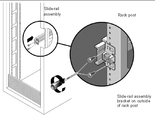
4. Repeat Step 1 through Step 3 for the remaining slide-rail assembly.
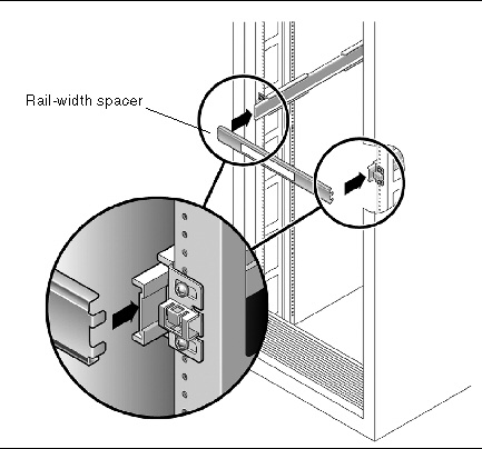
5. From the front of the rack, set the proper width of the rails with the rail-width spacer. (See FIGURE 2-4.)
| Note - The rail-width spacer, shown in FIGURE 2-4, is shipped with the bolt-on rail kit. Use it to set the rails to the proper width, then remove it. |
a. Insert the rail-width spacer into the slot on the inside of the slide rails.
b. Tighten the screws to lock the rails firmly to the rack posts.
c. Remove the rail-width spacer.
d. Confirm that the rails are attached firmly to the rack.
FIGURE 2-4 Setting the Rail Width on the Front of the System
6. Repeat Step 5 for rear of the rack.
On the rear of the rack, the slots for the rail-width spacer are on the inside of the rails, several inches from the ends.
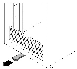
7. If your rack includes an anti-tip foot, extend it from the bottom of the rack. (See FIGURE 2-5.)
An anti-tip foot is typically required on racks that are not bolted in place.

|
Caution - If your rack requires an anti-tip foot, and it is not extended, the rack could tip over. |
FIGURE 2-5 Extending the Anti-tip Foot
Use this procedure to install the server chassis, with mounting brackets, into the slide-rail assemblies that are mounted to the rack.
|
|
Caution - This procedure requires a minimum of two people because of the weight of the server. Attempting this procedure alone could result in equipment damage or personal injury. |
|
|
Caution - Always load equipment into a rack from the bottom up so that it will not become top-heavy and tip over. |
1. Push the slide rails into the slide-rail assemblies in the rack as far as possible.
2. Raise the server so that the rear ends of the mounting brackets are aligned with the slide-rail assemblies that are mounted in the equipment rack. (See FIGURE 2-6.)
3. Insert the server with mounting brackets into the slide rails, then push the server into the rack slowly, until the mounting brackets meet the slide-rail stops (approximately 12 inches, or 30 cm).
Push the server with mounting brackets gently. It will stop abruptly.
FIGURE 2-6 Inserting the Server With Mounting Brackets Into the Slide Rails
(Sun Fire X4140 Server Shown)
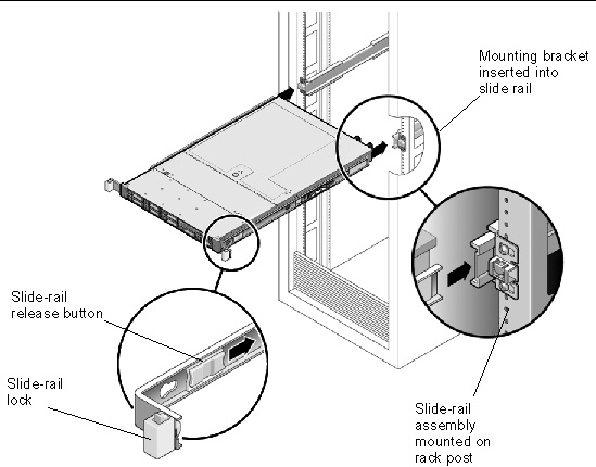
4. Simultaneously push both slide-rail release buttons towards the back of the rack, while pushing the server into the rack. (See FIGURE 2-6.)
5. Continue pushing until the front of the server is flush with the rack posts.
The slide-rail lock will latch, securing the server in place with an audible click.
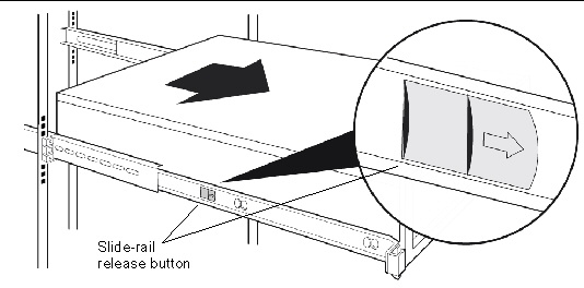
6. Verify that the slide rails work correctly. See FIGURE 2-7.
a. Press the slide-rail release buttons while pulling the server out from the rack.
The server should slide about half way out of the rack, then stop.
b. Simultaneously press the gray slide rail release tabs while pulling the server further out from the rack.
The server should pull the rest of the way out of the rack, until the slide rails are fully extended.
FIGURE 2-7 Location of Slide Rail Release Tabs
|
|
Caution - Verify that the server is securely mounted in the rack and that the slide-rail locks are engaged with the mounting brackets before continuing. |
c. Once you have verified the function of the slide rails, slide the server back fully into the rack until the slide-rail lock engages.
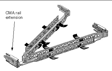
Use this procedure to install an optional cable management arm (CMA). FIGURE 2-8 shows the CMA.
FIGURE 2-8 Cable Management Arm (CMA)
2. Take the CMA to the back of the equipment rack and ensure that you have adequate room to work around the back of the server.
| Note - References to “left” or “right” in this procedure assume that you are facing the back of the equipment rack. |
3. If the CMA rail extension is taped to the CMA arm, remove the tape.
4. Attach the CMA rail extension to the left slide rail until the extension locks into place with an audible click. (See FIGURE 2-9.)
FIGURE 2-9 Inserting the CMA Rail Extension Into the Back of the Left Slide Rail
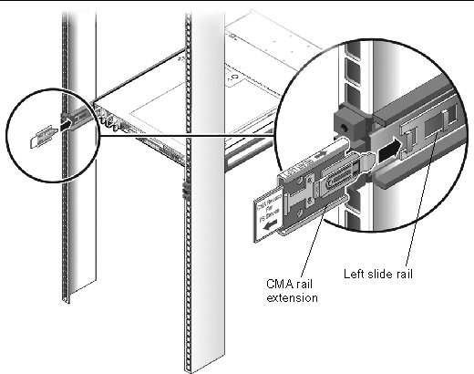
5. Verify that the CMA rail extension engages the slide rail, as shown in FIGURE 2-9.
| Note - Support the CMA in the remaining installation steps. Do not allow the arm to hang by its own weight until it is secured by all three attachment points. |
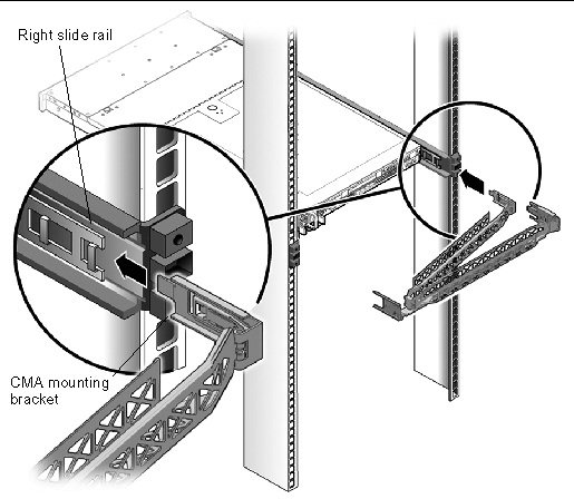
6. Insert the CMA’s mounting bracket connector into the right slide rail until the connector locks into place with an audible click. (See FIGURE 2-10.)
FIGURE 2-10 Inserting the CMA Mounting Bracket Into the Back of the Right Slide Rail
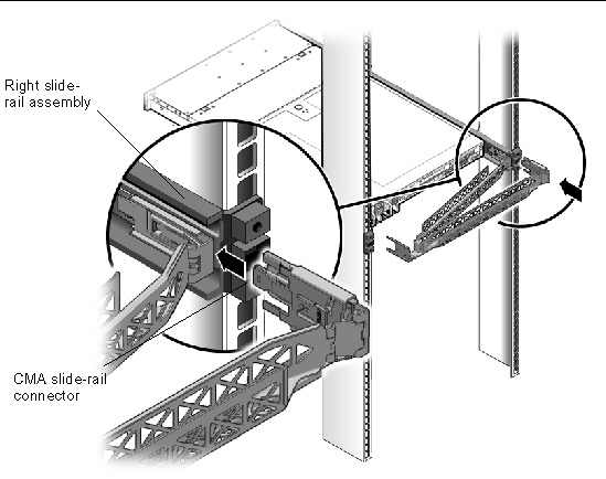
7. Insert the right CMA slide-rail connector into the right slide-rail assembly until the connector locks into place with an audible click. (See FIGURE 2-11.)
FIGURE 2-11 Inserting CMA Slide-Rail Connector Into the Back of the Right Slide-Rail Assembly
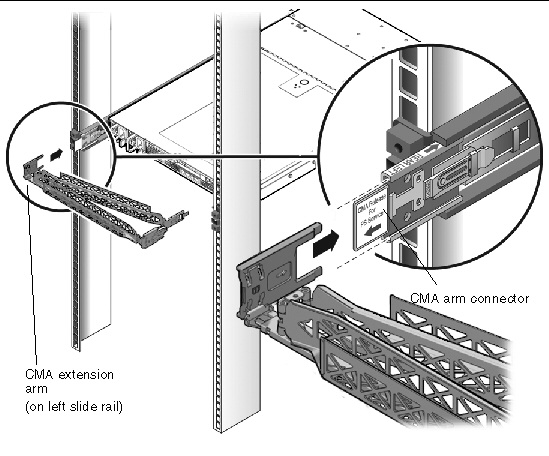
8. Insert the left CMA slide-rail connector into the rail extension on the left slide-rail assembly until the connector locks into place with an audible click. (See FIGURE 2-12.)
FIGURE 2-12 Connecting the CMA Arm to the Rail Extension Connector
9. Install and route cables to your server, as required.
10. Attach the hook and loop straps to the CMA, and press them into place to secure the cables. (See FIGURE 2-13.)
For best results, place three hangers, evenly spaced, on the rear-facing side of the CMA and three on the side facing the server.
FIGURE 2-13 Installing CMA Cable Straps

11. Attach the right outer latch.
12. Attach the support latch to the left CMA extension.
Use this procedure to ensure that the slide rails and CMA are operating correctly.
| Note - Two people are recommended for this procedure: one to move the server into and out of the rack, and one to observe the cables and CMA. |
1. Slowly pull the server out of the rack until the slide rails reach their stops.
2. Inspect the attached cables for any binding or kinks.
3. Verify that the CMA extends fully from the slide rails.
4. Push the server back into the rack, as described in the following sub-steps.
When the server is fully extended, you must release two sets of slide-rail stops to return the server to the rack:
a. The first set of stops are released by sliding the green release mechanism, located on the inside of each slide rail, just behind the back panel of the server. Push in both sides simultaneously and slide the server toward the rack.
The server will slide in approximately 18 inches (46 cm) and stop.
Verify that the cables and the CMA retract without binding before you continue.
b. The second set of stops are the slide-rail release buttons, located near the front of each mounting bracket. See FIGURE 2-6. Simultaneously push or pull both of the slide-rail release buttons, and push the server completely into the rack until both slide-rail locks engage.
c. Adjust the cable straps and CMA as required.
Connect cables to the server as described in the following sections.
Refer to Cabling Notes for Sun Fire X4140, X4240, and X4440 Servers.
| Note - When you are finished connecting the cables to the server, ensure that the server can slide smoothly into and out of the rack without binding or damaging the cables. See the section, Verifying Operation of the Slide Rails and CMA. |
FIGURE 2-14 shows the connectors on the rear panel of the server.
FIGURE 2-14 Sun Fire X4140 Rear Panel Features

The Sun Fire X4140 server has four RJ-45 Gigabit Ethernet connectors, marked NET0, NET1, NET2, and NET3 (FIGURE 2-14).
1. Connect a Category 5 cable from your network switch or hub to Ethernet Port 0 (NET0) on the rear of the chassis.
2. Connect Category 5 cables from your network switch or hub to the remaining Ethernet ports (NET1, NET2, NET3), as needed.
The serial management port is marked SER MGT (FIGURE 2-15). It provides a serial connection to the service processor.
FIGURE 2-15 Serial and Network Ports - Rear of Chassis

| Note - Use the serial management port only for server management. It is the default connection between the service processor and a terminal or a computer. |
|
|
Caution - Do not attach a modem to this port. |
 Connect a Category 5 cable from the SER MGT serial management port to the terminal device.
When connecting either a DB-9 or a DB-25 cable, use an adapter to perform the crossovers given for each connector.
The default serial protocol is 9600 baud, no parity, with no hardware or software flow control.
The SP network management port is marked NET MGT (FIGURE 2-15). It provides a network connection to the service processor.
| Note - The network management port is configured by default to retrieve network settings via Dynamic Host Configuration Protocol (DHCP), and to allow connections using Solaris Secure Shell (SSH). You might need to modify these settings for your network. Instructions are given in Chapter 5. |
Connect a Category 5 cable from the NET MGT network management port to your network switch or hub.
Connect AC power cables to power supply 0 and power supply 1, as shown in FIGURE 2-14.
|
|
Caution - Do not turn on system power yet. |
When you connect AC power to the server, the server automatically enters standby power mode. The service processor starts, but the server remains powered off.
The Power/OK LED on the front panel flashes.
| Note - When the CMA is installed, it covers the AC power connectors. To access the power connectors, release the CMA arm connector on the left side of the CMA, and swing the CMA out of the way. See FIGURE 2-12. |
For more complete information about powering the system on and off, see Chapter 6.
The video port connector uses a HD-15 connector, which is located at the lower right corner of the rear panel (FIGURE 2-14).
Four Universal Serial Bus (USB) ports are provided. USB ports 0 and 1 are located on the rear of the chassis (FIGURE 2-14). Ports 2 and 3 on the front of the chassis.
Connect cables to the server as described in the following sections.
Refer to Cabling Notes for Sun Fire X4140, X4240, and X4440 Servers.
| Note - When you are finished connecting the cables to the server, ensure that the server can slide smoothly in and out of the rack without binding or damaging the cables. See the section, Verifying Operation of the Slide Rails and CMA. |
FIGURE 2-16 shows the connectors and power supplies on the back of the Sun Fire X4240 and X4440 servers.
FIGURE 2-16 Sun Fire X4240 and X4440 Rear Panel Features

USB ports 2 and 3 are located on the front panel (FIGURE 2-17).
FIGURE 2-17 Sun Fire X4240 and X4440 Front Panel USB Ports

The servers have four RJ-45 Gigabit Ethernet network connectors. They are marked NET0, NET1, NET2, and NET3 (FIGURE 2-18).
FIGURE 2-18 Ethernet Network Connections

1. Connect a Category 5 cable from your network switch or hub to Ethernet Port 0 (NET0) on the rear of the chassis.
2. As needed, connect Category 5 cables from your network switch or hub to the remaining Ethernet ports (NET1, NET2, NET3).
The serial management port is marked SER MGT (FIGURE 2-18). It is the leftmost RJ-45 port on the rear of the chassis.
This port provides a serial connection to the service processor.
| Note - Use the serial management port only for server management. It is the default connection between the service processor and a terminal or a computer. |
|
|
Caution - Do not attach a modem to this port. |
Connect a Category 5 cable from the serial management port to the terminal device.
When connecting either a DB-9 or a DB-25 cable, use an adapter to perform the crossovers given for each connector.
The SP network management port is marked NET MGT (FIGURE 2-18). It provides a network connection to the service processor. It is the RJ-45 port above the rear USB ports.
Connect a Category 5 cable from your network switch or hub to the Network Management Port.
| Note - This port is not operational until you configure the network settings (through the serial management port), as described in Chapter 5. |
| Note - The network management port is configured by default to retrieve network settings via Dynamic Host Configuration Protocol (DHCP) and to allow connections using Solaris Secure Shell (SSH). You might need to modify these settings for your network. Instructions are given in Chapter 5. |
Connect AC power cables to power supply 0 and power supply 1. See FIGURE 2-18.
|
|
Caution - Do not turn on system power yet. |
When you connect AC power to the server, the server automatically enters power mode. The service processor starts, but the server remains powered off.
The Power/OK LED on the front panel flashes.
| Note - When the CMA is installed, it covers the AC power connectors. To access the power connectors, release the CMA arm connector on the left side of the CMA, and swing the CMA out of the way. See FIGURE 2-12. |
For more complete information about powering the system on and off, see Chapter 6.
The video port connector uses a HD-15 connector, which is located at the lower right corner of the rear panel (FIGURE 2-16).
Four Universal Serial Bus (USB) ports are provided. USB ports 0 and 1 are located on the rear of the chassis (FIGURE 2-16). Ports 2 and 3 are on the front of the chassis (FIGURE 2-17).
| Sun Fire X4140, X4240 and X4440 Servers Installation Guide | 820-2394-13 |
Copyright © 2009 Sun Microsystems, Inc. All rights reserved.