Sun Fire X4240 Server Overview
|
This chapter provides an overview of the features of the Sun Fire X4240.
The following information is included:
1.1 Product Description
The Sun Fire X4240 Server is an enterprise-class two-socket rackmount x64 system powered by AMD Opteron processors, packing high performance and room for growth with six PCIe slots and 16 DIMM slots into a compact 2-RU footprint.
The product features are listed in TABLE 1-1.
TABLE 1-1 Sun Fire X4240 Server System Features
|
Feature
|
Description (Sun Fire X4240)
|
|
Processor
|
AMD64 Opteron Socket F [1207] (1MByte L2 cache per processor chip). Supports Dual and Quad core.
|
|
Memory
|
- 8 DDR-2 DIMM slots per socket. Up to 800 MHz memory speeds depending upon processor type and memory configuration.
- PC2-4200R 533 MHz registered DIMMs with ECC
- PC2-5300R 667 MHz registered DIMMs with ECC
- PC2-6400R 800 MHz registered DIMMs with ECC
- 1 GB, 2 GB, 4 GB, or 8 GB per DIMM
- See DDR2 DIMM Guidelines.
|
|
Ethernet ports
|
4 ports, 10/100/1000 Mbps, auto-negotiating through two separate controllers
|
|
Internal drives
|
- SAS (up to 16) or SATA (up to 8 SSD) disk drives.
- Up to 16 SFF SAS 73-GB or 146-GB 2.5-inch form factor drives.
- Support for hardware-embedded RAID 0 (striping) and RAID 1 (mirroring)
- Optional RAID Levels 0, 1, IE, 5, 5EE, 6, 10, 50, and 60
|
|
Removable media
|
1 slimline DVD drive, supporting CD-R/W, CD+R/W, DVD-R/W, DVD+R/W
|
|
USB ports
|
5 USB 2.0 ports: 2 in front, 2 in rear, plus 1 internal USB port
|
|
Service ports
|
- 1 RJ-45 serial management port (SER MGT) (default connection to access service processor)
- 1 10-MB network management port (NET MGT) (to access service processor)
- HD15 VGA video port
|
|
Cooling
|
- 6 hot-swappable system fan modules (2 fans per module)
- An air duct facilitates processor/memory airflow
|
|
PCI interfaces
|
6 standard low-profile PCIe slots on three riser boards (1 -x4, 4 - x8 and 1 - x4 electrical / 5 - x16 and 1 - x8 mechanical)
See Sun Fire X4240 PCIe Card Guidelines.
|
|
Power
|
- AC power: 100-240 VAC, 12-5A, 50-60Hz
- 1 or 2 hot-swappable 1050W power supply units (PSUs) to provide N+N redundancy, with energy efficient design
|
|
Remote management
|
On-board integrated LOM service processor providing:
- DMTF CLP-based Command Line Interface (CLI) over SSH
- Web-based browser interface GUI over HTTPS
- IPMI 2.0
- SNMP (v1, v2c, and v3)
- Remote graphical access (remote KVM) over Ethernet
- Remote storage over Ethernet
|
|
Operating system
|
Solaris 10, Update 6 10, Update 6
Solaris 10 OS with specific Sun Fire X4240 Server software components
Supports:
 Red Hat Enterprise Linux 4.7 (AS) (32-bit/64-bit) Red Hat Enterprise Linux 4.7 (AS) (32-bit/64-bit)
Red Hat Enterprise Linux 5.3 (64-bit)
SUSE Linux Enterprise Server 10 SP2 (64-bit)
VMware ESX 3.0.3, ESX 3.5, ESXi 3.5
Windows Server 2003 x32 SP2 or greater (Standard Edition/ Enterprise Edition)
Note - OSes change frequently. Refer to your product web page for updates.
|
|
Other software
|
Java Enterprise System with a 90-day trial license
|
1.2 Sun Fire X4240 Server Chassis Overview
The Sun Fire X4240 Server is based on an all-new chassis family.
1.2.1 Infrastructure Boards
The Sun Fire X4240 has the following boards installed in the chassis. The boards are listed in TABLE 1-2.
TABLE 1-2 Infrastructure Boards
|
Board
|
Description
|
Reference
|
|
Motherboard
FRU
|
The motherboard includes processor modules, slots for 16 DIMMs, memory control subsystems, and the service processor (iLOM) subsystem.
The service processor (integrated LOM) subsystem controls the host power and monitors host system events (power and environmental). The integrated LOM controller draws power from the host’s 3.3V standby supply rail, which is available whenever the system is receiving AC input power, even when the system is turned off.
|
Servicing the Motherboard Assembly
Refer to the Sun Fire 4140, 4240 and 4440 ILOM Supplement for iLOM sensor information.
|
|
Power distribution board
FRU
|
This board distributes main 12V power from the power supplies to the rest of the system. It is directly connected to the paddle card, and to the motherboard via a bus bar and ribbon cable. It also supports a top cover interlock (“kill”) switch.
In the Sun Fire X4240, the power supplies connect directly to the power distribution board.
|
Servicing the Power Distribution Board (PDB)
|
|
Paddle card
FRU
|
This board serves as the interconnect between the power distribution board and the fan power boards, drives backplane, and I/O board.
|
Servicing the Paddle Card
|
|
Fan power boards (2)
FRU
|
These boards carry power to the system fan modules. In addition, they contain fan module status LEDs, and transfer I2C data for the fan modules.
|
Servicing the Fan Power Boards
|
|
Drives backplane
FRU
|
This board includes the connectors for the drives, as well as the interconnect for the I/O board, Power and Locator buttons, and system/component status LEDs. The Sun Fire X4240 has a 16-disk backplane. Each drive has an LED for power/activity, fault, and ok-to-remove.
|
Servicing the Hard Drive Backplane
|
|
Front I/O board
FRU
|
This board carries the front panel USB connections from the drives backplane. The board connects directly to the drives backplane. It is packaged with the DVD drive as a single unit.
|
Servicing the DVD/USB Module
|
|
PCIe risers
FRU
|
In the Sun Fire X4240, each riser supports two PCIe cards. There are three risers per system, each attached to the rear of the motherboard.
|
Servicing PCIe Risers
|
1.2.2 System Cables
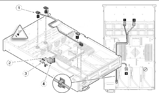
The Sun Fire X4240 internal cables are listed in TABLE 1-3. FIGURE 1-1 shows the SAS cables on the Sun Fire X4240.
FIGURE 1-1 Cables (SAS)
 [ D ]
[ D ]
TABLE 1-3 Sun Fire X4240 Server Cables (SAS)
|
|
Cable
|
Connects...
|
|
1
|
Drives data cables (2)
|
Between the motherboard (or optional HBA PCI-Express Card) and the drives backplane
|
|
2
|
Motherboard to PDB cable
|
Between the power distribution board and the motherboard
|
|
3
|
Top cover interlock cable
|
To the power distribution board
|
|
4
|
PSU backplane cable
|
To the power supply units
|
FIGURE 1-2 shows the SAS cables on a diskless Sun Fire X4240.
FIGURE 1-2 Cables (Diskless Configuration)

Figure Legend Sun Fire X4240 Server Cables (Diskless Configuration)
|
|
Cable
|
Connects...
|
|
1
|
Drives data cables (2)
|
Between the motherboard (or optional HBA PCI-Express Card) and the drives backplane
|
|
2
|
Motherboard to PDB cable
|
Between the power distribution board and the motherboard
|
|
3
|
PSU backplane cable
|
To the power supply units
|
|
4
|
Top cover interlock cable
|
To the power distribution board
|
1.2.3 Dimensions
The 2U chassis form factor dimensions are listed in TABLE 1-4.
TABLE 1-4 Sun Fire X4240 Server Dimensions
|
Dimension
|
Sun Fire X4240
|
|
Height
|
87.85 mm/3.46 inches
|
|
Width
|
445.71 mm/17.55 inches (includes ears - chassis is 425.46 mm/ 16.75 inches)
|
|
Depth
|
733.65 mm/28.88 inches
(includes PSU handle - the chassis is 711.25 mm/28.00 inches)
|
|
Weight
|
Maximum: 25.6 kg/56.3 pounds.
|
1.3 Sun Fire X4240 Front Panel Features
FIGURE 1-3 shows front panel features on the Sun Fire X4240.
FIGURE 1-3 Front Panel Features

Figure Legend
|
1
|
Locator LED/Locator button (white)
|
5
|
Power Supply Service Required LED (amber)
|
|
2
|
Service Action Required LED (amber)
|
6
|
System Overtemperature LED (amber)
|
|
3
|
Power/OK LED (green)
|
7
|
Fan Module Service Required LED (amber)
|
|
4
|
Power button
|
8
|
Drives map
|
1.4 Sun Fire X4240 Rear Panel Features
FIGURE 1-4 shows rear panel features on the Sun Fire X4240. For more detailed information about ports and their uses, see the Sun Fire X4240 Server Installation Guide. For a detailed description of PCIe slots, see Servicing PCIe Risers.
FIGURE 1-4 Rear Panel Features

Figure Legend
|
1
|
PSU 1
|
9
|
Rear Panel System Status LEDs
Locator LED/Locator button (white)
Service Action Required LED (amber)
Power/OK LED (green)
|
|
2
|
PSU 0
|
10
|
Serial Management Port
|
|
3
|
PCIe 3
|
11
|
Network Management Port
|
|
4
|
PCIe 0
|
|
NMI button (Behind panel, not shown)
|
|
5
|
PCIe 4
|
|
Reset Button (Behind panel, not shown)
|
|
6
|
PCIe 1
|
12
|
Gbit Ethernet Ports (0, 1, 2, 3)
|
|
7
|
PCIe 5
|
13
|
USB Ports (0, 1)
|
|
8
|
PCIe 2
|
14
|
HD15 Video Port
|
1.5 Illustrated Parts Breakdown
The following illustrations provide exploded views of system components. Use these illustrations, and the accompanying tables, to identify parts in your system.
FIGURE 1-5 I/O Components (Sun Fire X4240)

Figure Legend
|
1
|
Top Cover
|
5
|
Drives
|
|
2
|
Hard Disk Backplane
|
6
|
DVD/USB Module
|
|
3
|
Hard Disk Cage
|
7
|
Left Control Panel Light Pipe Assembly
|
|
4
|
Left Control Panel Light Pipe Assembly
|
|
|
FIGURE 1-6 Power Distribution/Fan Module Components (Sun Fire X4240)

Figure Legend
|
1
|
Paddle Card
|
5
|
Fan Modules
|
|
2
|
Power Distribution Board/Bus Bar Assembly
|
6
|
Fan Boards
|
|
3
|
Paddle Card
|
7
|
Air Baffle
|
|
4
|
Power Supplies
|
|
|
| Note - System cooling might be affected by dust and contaminant build-up. It is recommended that systems be opened and checked approximately every six months or more often in dirty operating environments. Check system heat sinks, fans, and air openings. If necessary, clean systems by brushing or blowing contaminants or carefully vacuuming contaminants from the system.
|
| Sun Fire X4240 Server Service Manual
|
820-3835-14
|
   
|
Copyright © 2010, Oracle and/or its affiliates. All rights reserved.