| Sun Fire X4500/X4540 Server Installation Guide |
| C H A P T E R 1 |
|
Installing the Sun Fire X4500/X4540 Server Hardware |
This chapter covers the following topics:
The Sun Fire X4500/X4540 Server documentation set contains several manuals. Before you start setting up your server, familiarize yourself with the major documents. The documentation set will grow as new features (such as OS support) are added.
In your system box, in addition to your server and power cords, you will find the following items:
 Bootable Diagnostics CD
After unpacking your server, perform the following tasks:
1. Install the server into a rack using orderable slide rails.
2. Install the cable management arm.
3. Install the cable management arm (X4540).
4. Remove the system from the rack.
7. Perform initial service processor configuration through the Integrated Lights Out Manager (ILOM).
8. Configure the preinstalled Solaris operating system.
TABLE 1-1 lists the qualified part numbers for these components. These ordering numbers are subject to change over time. For an updated list of components, see the following web site:
http://sunsolve.sun.com/handbook_pub/Systems/
At least three people are needed to install the system into the rack:
| Note - This assumes a mechanical lift is used. If a mechanical lift is not available, the system must be depopulated of most components. |

|
Caution - To prevent injury to staff or damage to the equipment, use extreme caution when installing the server. |
Because of the weight of the server, it is important to use a mechanical lift for installing the server into the rack.
If a lift is not available, remove the following components to reduce the weight:
|
|
Caution - Label the 46 hard drives before you remove them and make sure they are replaced in the same slot from which they were removed. |
| Note - Leave the fan trays installed. |
|
|
Caution - This assumes a mechanical lift is used. If a mechanical lift is not available, the server must be depopulated of most components. |
| Note - Because of its depth, the Sun Fire X4500/X4540 server fits best in 1000 mm racks. Use the Sun Rack 1000-42 and Sun Rack 1000-38. |
The Sun Fire X4500/X4540 server slide rails are compatible with a wide range of equipment racks that meet the following standards:
For more information on Sun racks, see:
http://www.sun.com/servers/rack/index.html
If your system is shipped with a Cable Management Arm (CMA), it is provided to protect the IO and power cables from damage when sliding the system in and out of a rack. If your system is shipped with a CMA, failure to use the CMA could result in damage to power or data cables during system servicing. The CMA kit includes the following:
1. If your system includes a CMA, unpack the CMA parts and take them to the rear of the equipment rack.
| Note - References to “left” or “right” in this procedure assume that you are facing the rear of the equipment rack. |
2. If the system is not fully installed into the rack, slide the system so that it is fully installed until it reaches the internal stops.
3. Attach the CMA-to-chassis bracket to the right side of the system. See FIGURE 1-1.
Use a #2 Phillips screwdriver to tighten all three screws.
a. Fasten the top two screws of the CMA bracket, then the bottom screw.
b. Turn each screw until it stops (do not overtighten).
Once the bracket is in place, you can install the CMA.
FIGURE 1-1 Installing the Outer Rail Extension

The CMA arrives in shipment with the ends folded under and tucked beneath the velcro flaps. Open the velcro flaps and unfold the CMA. As the CMA is installed into the rack, it is folded at an angle. See FIGURE 1-2.
4. Fold the CMA as seen in FIGURE 1-2.

5. Insert the CMA hinge plate into the CMA bracket. (See FIGURE 1-3.) Pull the green, spring-loaded pin outwards, slide the hinge-plate (marked #2) into the CMA bracket, and release the pin. Verify that the hinge-plate is fully seated into the CMA bracket.
FIGURE 1-3 Inserting the Right CMA Hinge Plate Into the CMA Bracket

6. Holding the left CMA hinge plate (marked #2), pull the green spring-loaded pin outwards and slide the hinge plate into the end of the left slide rail (see FIGURE 1-4). Release the pin and verify that the CMA is firmly attached to the rail.
FIGURE 1-4 Installing CMA Arm Into Left Side Rail

7. Open the CMA assembly and pull into a U shape. See FIGURE 1-5.
8. Loosen all the velcro straps before handling the cables.
9. Install cables to your system, as required, and route the cables through the CMA cable hangers. Both power supply cords and any data cables (such as Ethernet cables) must be run through the CMA.
To minimize electrical interference, the power cables can be placed at the bottom of the CMA trough and data cables tie-wrapped to the top of the trough.
Pull the cables all the way over to the far right side to enter the CMA. This is to help ensure equal tension and a service loop on cables during operation.
FIGURE 1-5 Example Cabling Path Through CMA Arms With Straps

| Note - Do not run cables from another system through the CMA. Use one CMA per system. |
10. Fold the CMA arms after cabling to prevent them from extruding into the aisle. See FIGURE 1-6.
FIGURE 1-6 Folding CMA Arm After Cabling

1. Inspect the attached cables for any binding or kinks.
2. Verify that the CMA extends and does not bind in the slide rails.
3. Make sure that the power cord cables are secured to the chassis with the clips on each power supply.
4. Adjust the cable hangers and CMA as required, and then retest the operation of the slide rails and CMA.
| Tip - To maximize airflow, tie-wrap the power cords at the bottom of the CMA troughs and the data cables at the top of these troughs. |
If you need to access the system controller (SC), first remove the CMA.
1. Unplug the power and data cables from the system.
2. Pull the green pins on each hinge plate and pull the CMA to the rear.
The cables can remain in the CMA and hang in place if it’s being removed only to service the SC module.
If your system is shipped with a Cable Management Arm (CMA), it is provided to protect the IO and power cables from damage when sliding the system in and out of a rack. If your system is shipped with a CMA, failure to use the CMA could result in damage to power or data cables during system servicing.
The CMA kit includes the following:
| Note - To protect your SAS cables from damage, use the Cable Management Bar (CMB) that comes with your system. See Installing the Sun Fire X4500/X4540 Server Hardware. |
| Note - For documentation on installing the Cable Management Bar, see Installing the Cable Management Bar (CMB). |
1. Label your cables so they are easy to identify when you need to reconnect them.
2. Unpack the CMA parts and take them to the rear of the equipment rack.
| Note - References to “left” or “right” in this procedure assume that you are facing the rear of the equipment rack. |
3. If the system is not fully installed into the rack, slide the system so that it is fully installed and it reaches the internal stops.
4. Attach the CMA-to-chassis bracket to the right side of the system. See FIGURE 1-7:
Use a #2 Phillips screwdriver to tighten the two captive screws on the bracket (do not overtighten).
FIGURE 1-7 Attaching the CMA-to-Chassis Bracket to the Chassis

The CMA arrives in shipment folded and secured by the velcro flaps which may need to be loosened or undone to allow the CMA freedom of movement.
5. Fold the CMA as seen in FIGURE 1-8.

6. Insert the CMA hinge plate into the CMA bracket while pulling the green, spring-loaded pin outwards. Slide the hinge-plate into the CMA bracket and release the pin. Verify the hinge-plate is fully seated into the CMA bracket.
FIGURE 1-9 Inserting the Right-side CMA Hinge Plate Into the CMA Bracket

7. Hold the left CMA hinge plate while pulling the green spring-loaded pin outwards. Slide the hinge plate into the end of the left slide rail. Release the pin and verify the CMA is firmly attached to the rail.
EXAMPLE 1-1 Installing Left Side CMA Arm Into Left Side Rail

8. Unfold the CMA assembly and pull into a U shape. See FIGURE 1-5.
9. Loosen all the velcro straps before handling the cables.
10. Install cables to your system, as required, and route the cables through the CMA cable hangers. Both power supply cords and any data cables (such as Ethernet cables) must be run through the CMA.
To minimize electrical interference, tie-wrap the power cables to the bottom of the CMA trough and tie-wrap the data cables to the top of the trough.
Route the cables toward the right to enter the CMA. This helps ensure equal tension on the cables and creates a service loop on the cables during operation.
FIGURE 1-10 Cabling Path Through CMA Arms With Straps
| Note - Do not run cables from another system through the CMA. Use one CMA per system. |
11. Fold the CMA after routing cables to prevent the CMA from protruding into the aisle. See FIGURE 1-6.
FIGURE 1-11 Folding CMA After Cabling

1. Inspect the attached cables for any binding or kinks.
2. Verify that the CMA extends and does not bind in the slide-rails.
3. Make sure that the power cords are secured to the chassis with the clips on each power supply.
4. Adjust the cable hangers and CMA as required, and then retest the operation of the slide-rails and CMA.
| Tip - To maximize airflow, tie-wrap the power cords at the bottom of the CMA troughs and the data cables at the top of these troughs. |
If you need to access the system controller (SC), first remove the CMA.
1. Unplug the power and data cables from the system.
2. Remove the Cable Management Bar.
3. Pull the green pins on each hinge plate of the CMA and pull the CMA to the rear.
The cables can remain in the CMA and hang in place if it’s being removed just to service the SC module.
The Cable Management Bar (CMB) is provided to protect the SAS cables from damage when sliding the system in and out of a rack.
The CMB kit includes the following:
| Note - To access some components, you must first remove the Cable Management Arm and Cable Management Bar. |
To begin this procedure, the Cable Management Arm (CMA) must be installed. To install the CMA, see Installing the Cable Management Arm (CMA) for the X4540.
1. Label your SAS cables so they are easy to identify when you need to reconnect them.
2. Unpack the CMB parts and assemble it by attaching the right and left brackets to either end of the bar.
FIGURE 1-12 Assembling the Cable Management Bar

| Note - References to “left” or “right” in this procedure assume that you are facing the rear of the equipment rack. |
3. If the system is not fully installed into the rack, slide the system so that it is fully installed and it reaches the internal stops.
4. Take the CMB assembly to the rear of the equipment rack.
5. Hold the left CMB bracket while pulling the green spring-loaded pin outwards. Slide the hinge plate into the end of the left bracket of the CMA. Release the pin and verify that the CMA is firmly attached to the rail.
EXAMPLE 1-2 Attaching the Right CMA Bracket

6. Hold the right CMB bracket while pulling the green spring-loaded pin outwards. Slide the hinge plate into the right end of the slide rail. Release the pin and verify the CMA is firmly attached to the rail.
7. Install the left hinge plate into the left hinge plate of the already installed CMA while pulling the green spring-loaded pin outwards. Slide the hinge plate into the left end of the slide rail. Release the pin and verify that the CMA is firmly attached to the rail.
FIGURE 1-13 Attaching the Left CMB Bracket

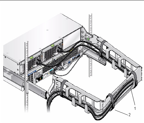
8. Route the SAS cables over the Cable Management Bar and to the PCI-e card connectors on the back panel of the system.
FIGURE 1-14 Installing SAS Cables onto a System with the CMB

1. Uninstall the left hinge plate by pulling the green spring-loaded pin outwards and pulling the hinge plate at the same time.
2. Uninstall the right hinge plate by pulling the green spring-loaded pin outwards and pulling the hinge plate at the same time.
This procedure assumes that you have turned off the server, removed the cable management arm, and removed any cables or cords that would restrict the movement of the server.
1. Remove the CMA and all the cables.
2. If you do not have a mechanical lift, remove the following components from the rear of the rack to reduce the weight to a safe level for manual lifting:
3. Completely extend the system until it stops against internal locks and stops.
4. Release the system using the latches on each side.
5. If you do not have a mechanical lift, open the drives access cover and remove the drives.
|
|
Caution - Make sure you label the drives so you can replace them in their original locations. |
6. Slide the system completely out of the slide rails and place on a clean, stable surface.
Attach cables to the back panel connectors of your server as required. See FIGURE 1-15.
FIGURE 1-15 Sun Fire X4500 Server Back Panel

FIGURE 1-16 Sun Fire X4540 Server Back Panel

1. If desired, connect a USB keyboard cable to a USB connector on the back panel or to the front panel. See FIGURE 1-15 and FIGURE 1-18.
2. (Optional) Connect a USB mouse cable to a USB connector or to the front panel. See FIGURE 1-18.
3. (Optional) Connect a video monitor cable to the video connector.
4. Connect Ethernet cables to the NET connectors as required for your Gigabit Ethernet.
5. If you plan to access the Integrated Lights Out Manager (ILOM) over the network, connect a network cable to the 10/100 Ethernet port labeled NET MGT.
6. If you plan to access the ILOM command-line interface using the serial management port, connect a compatible cable to the RJ-45 connector labeled, SER MGT.
The SER MGT port is the serial connection to the service processor and supports ILOM.
Observe the following considerations for the serial port and serial port cabling:
7. Continue with Powering On and Powering Off the Server.
The server has two levels of power: standby power and main power. For initial configuration of the service processor (SP), you need to apply standby power. The procedures for powering on to main power mode and for shutting down from main power mode are also included in this section.
|
Use this procedure to apply standby power to SP before initial configuration.
1. Connect a grounded AC power cord into the two AC power connectors on the back panel of the server and into grounded AC (200 VAC to 240 VAC) power outlets.
2. Ensure that grounded AC power cords are plugged into the two AC power connectors on the back panel of the server and into grounded AC (200 VAC to 240 VAC) power outlets.
When the power is connected, the server might take up to 58 seconds to go into standby power mode. In standby power mode, the Power/OK LED on the front panel and at the rear on the system controller blinks, indicating that the SP is working. For the LED location, see FIGURE 1-17.
3. Continue with initial software setup tasks, explained in Configuring the Sun Fire X4500/X4540 Server Through the Service Processor.
|
To power on main power for all server components:
1. Verify that power cords are connected and that standby power is on.
In standby power mode, the Power/OK LED (3) on the front panel blinks.
FIGURE 1-17 Sun Fire X4500/X4540 Server Power Button

| Note - See the service label on the drives access cover for an explanation of the LEDs on the drives, fans, power supply, and system controller. |
2. Use a nonconducting stylus to press and release the recessed Power button on the server front panel. See FIGURE 1-17.
When main power is applied to the full server, the Power/OK LED next to the Power button lights and remains lit.
FIGURE 1-18 Sun Fire X4500/X4540 Server Front Panel

|
 To power off the server from main power mode, use one of the following two methods:
Graceful shutdown: Use a nonconducting stylus to press and release the Power button on the front panel. This causes Advanced Configuration and Power Interface (ACPI) enabled operating systems to perform an orderly shutdown of the operating system. Servers not running ACPI-enabled operating systems go to standby power mode immediately.
Emergency shutdown: Press and hold the Power button for four seconds to force the main power off and to enter standby power mode.
When main power is off, the Power/OK LED on the front panel begins blinking, indicating that the server is in standby power mode.
|
|
Caution - To power off the server completely, you must disconnect the AC power cords from the power supplies at the rear of the server. |
| Sun Fire X4500/X4540 Server Installation Guide | 820-4855-12 |
Copyright © 2009 Sun Microsystems, Inc. All rights reserved.
 To Apply Standby Power for Initial Service Processor (SP) Configuration