| C H A P T E R 2 |
|
Configuring the Sun Fire X4500/X4540 Server Through the Service Processor |
This chapter explains how to connect to the server’s service processor (SP) so that you can perform initial configuration tasks. The SP supports the Integrated Lights Out Manager (ILOM) software that you can use to manage the server.
This chapter covers the following topics:
For additional information, see the ILOM documentation at:
http://docs.sun.com/app/docs/prod/sf.x4500
http://docs.sun.com/app/docs/prod/sf.x4540
To learn more about Integrated Lights Out Manager (ILOM), see the appropriate ILOM documentation:
| Note - The SP is installed in the system by default. |
The Sun Integrated Lights Out Manager (ILOM) software provides powerful tools for managing your Sun Fire X4500/X4540 server.
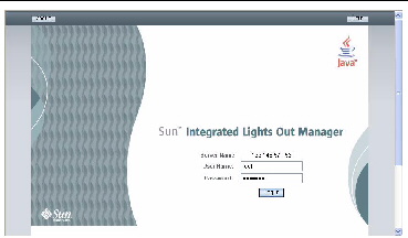
FIGURE 2-1 Integrated Lights Out Manager GUI Login Page

ILOM consists of four components, three of which are on your host server and one which can be used on the client system that accesses your host server.
The first three components are as follows:
These interfaces call the same underlying system management functions on your GRASP board, so you can choose to work with one or more of these ILOM interfaces to integrate with the other management interfaces running in your data center.
Note - The Remote Console application runs on the host server. On client systems, a web browser and Sun Java runtime environment version 5.0 or later are required. You can download the Java runtime environment for your client system for free from http://java.sun.com. runtime environment version 5.0 or later are required. You can download the Java runtime environment for your client system for free from http://java.sun.com.
|
The ILOM communicates through the system serial port or through a dedicated Ethernet port.
Connecting with the Ethernet requires some configuration.
There are two methods for connecting to the ILOM SP to perform initial setup and configuration:
You can access the ILOM CLI at any time by connecting a terminal or a PC running terminal emulation software to the RJ-45 serial port on the ILOM board.
Use this procedure to establish a serial connection to the ILOM SP so that you can perform initial configuration of ILOM.
| Note - This procedure assumes that you have already completed the hardware setup and have applied standby power to your server, as described in Chapter 1 of this guide. |
1. Verify that your terminal, laptop, or terminal server is operational.
2. Configure the terminal device or the terminal emulation software running on a laptop or PC to the following settings:
| Note - Connect a serial cable from the RJ-45 SERIAL MGT port on the server’s back panel to a terminal device. See FIGURE 1-15. The serial port requires that the serial cable connected to it use the following pin assignments. Note that these are the same as the serial cable connector for the Sun Advanced Lights Out Manager (ALOM) or Remote System Control (RSC). See TABLE 2-1. |
3. Press Enter on the terminal device.
This establishes the connection between the terminal device and the ILOM.
| Note - If you connect a terminal or emulator to the serial port before it has been powered up or during its power-up sequence, you will see bootup messages. |
When the system has booted, the ILOM displays its login prompt:
The first string in the prompt is the default host name. It consists of the prefix SUNSP and the ILOM’s MAC address. The MAC address for each ILOM is unique.
a. Type the default user name: root
b. Type the default password: changeme.
When you have successfully logged in, the SP displays the ILOM default command prompt:
The ILOM is now accessing the CLI. You can now run CLI commands.
For example, to display status information about the motherboard in your server, type the following command:
Use the ILOM commands to configure the server’s user accounts, network settings, access lists, alerts, and so on. For detailed instructions on CLI commands, see the Integrated Lights Out Manager 2.0 User’s Guide.
5. To go to the host serial console (host COM0), type the following commands:
| Note - After you have returned to the serial console, to switch back to the CLI, press the Escape and left parenthesis [ ( ] key in rapid succession. |
6. After configuring the server, continue with Configuring the Preinstalled Solaris Operating System.
To access the full range of ILOM functionality, you must connect a LAN to the Ethernet port and configure your Ethernet connection.
ILOM supports Dynamic Host Configuration Protocol (DHCP) and static IP addressing.
The BIOS Setup utility enables you to set the ILOM IP address and to configure it manually or to use DHCP.
1. Unpack your server and connect the system power cable to a power source.
Refer to your platform documentation for instructions on installing the hardware, cabling, and powering on.
2. If you plan to use DHCP, verify that your DHCP server is configured to accept new media access control (MAC) addresses.
1. Start the BIOS Setup utility.
b. When you see a boot message, press F2 to enter BIOS Setup.
After some messages and screen changes, the BIOS Setup utility is displayed.
The Advanced page is displayed.
3. Highlight IPMI 2.0 Configuration in the list, and then select Enter.
The IPMI 2.0 Configuration page is displayed.
4. Fill in the IPMI 2.0 Configuration page.
a. Under IP Assignment, select DHCP or Static.
b. If you selected Static, fill in the IP address, subnet mask, and default gateway at the bottom of the page.
5. Select Commit to save your changes.
If you selected DHCP, the BIOS utility automatically updates the address fields.

|
Caution - You must use Commit to save the changes on this page. Pressing F10 does not save your changes. |
To configure the ILOM to use a DHCP address:
1. Verify that your DHCP server is configured to accept new media access control (MAC) addresses.
2. Unpack your server and connect the system power cable to a power source.
3. Obtain the service processor MAC address from one of the following locations.
MAC addresses are 12-digit hexadecimal strings in the format xx:xx:xx:xx:xx:xx where x represents a single hexadecimal letter (0-9, A-F, a-f). Write down that address for future reference.
4. Connect an Ethernet cable to the RJ-45 NET MGT Ethernet port.
See FIGURE 1-15.
5. Assign an Ethernet address directly, or let DHCP assign one for you.
a. To assign your own Ethernet address, use the DHCP configuration software to assign an IP address to the MAC address noted in Step 3. See the DHCP server documentation for details.
b. To let DHCP assign an IP address:
When you connect an Ethernet cable to the ILOM, the ILOM provides its MAC address and DHCP assigns the ILOM an IP address.
i. Log in to your DHCP server and view its DHCP log file.
ii. Identify the IP address in the log file that corresponds to the ILOM MAC address.
Typically, DHCP log file entries are individual lines with the following comma-separated fields:
ID, Date, Time, Description, IP Address, Host Name, MAC Address
Locate the MAC address of your ILOM in the MAC Address (seventh) field of the correct DHCP file entry, and record the corresponding value of the IP Address (fifth) field. This is the IP address that you must use to access the web browser and the remote console.
When this procedure is complete, you can access the ILOM using the IP address assigned by DHCP.
Usually, you configure the ILOM to use DHCP, as described in Configuring ILOM Using DHCP.
If you choose to configure the ILOM using a static IP address, you can do so using one of these methods:
1. Unpack your server and connect the system power cable to a power source.
2. Obtain the ILOM IP address from one of the following locations. Record the IP address for future reference.
| Note - You can set the IP address using the BIOS Setup utility, IPMI 2.0 Configuration page. If the address you see there is acceptable, you do not need to change anything. To change the IP address, type the new address in the IP Address field and click Commit. See Configuring the IP Address Using the BIOS Setup Utility for details. |
To set a static IP address for the ILOM using the CLI and a serial line connection:
1. Establish a serial connection to the ILOM.
See Connecting to ILOM Using a Serial Connection for details.
3. Type the following command to set the working directory:
4. Type the following commands to specify a static Ethernet.
| Note - The following values are examples only. You must specify the IP address, netmask, and gateway appropriate for your ILOM and network configuration. |
set pendingipaddress=129.144.82.26
set pendingipnetmask=255.255.255.0
set pendingipgateway=129.144.82.254
1. Log in to the ILOM using Secure Shell (SSH) over the network, or by connecting a terminal to the serial port.
To establish an SSH connection to the CLI, type the appropriate connection command in the SSH application. For example, to connect to the SP with an IP address of 129.144.82.20, type the following command:
Use the IP address you obtained in Before You Begin.
2. Type the following command to set the working directory:
3. Type the following commands to specify a static Ethernet.
| Note - The following values are samples only. You must specify the IP address, netmask, and gateway appropriate for your ILOM and network configuration. |
set pendingipaddress=129.144.82.26
set pendingipnetmask=255.255.255.0
set pendingipgateway=129.144.82.254
To set a static IP address for the ILOM using the web browser, do the following. To access the full range of ILOM functionality such as the GUI, connect a LAN to the Ethernet port and configure your Ethernet connection.
1. Connect to the ILOM through a web browser running on a remote system.
Use the IP address you obtained in Before You Begin.
The default user name is root, and the default password is changeme.
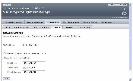
3. Choose the Configuration tab and its Network tab to display information about the current ILOM network configuration. See FIGURE 2-2.
4. Click the Use the Following IP Address option. See FIGURE 2-2.
FIGURE 2-2 Integrated Lights Out Manager Network Settings Page

5. Modify the displayed settings as required, and click save.
ILOM supports Dynamic Host Configuration Protocol (DHCP) and static IP addressing.
For information on how the disk mapping changes when upgrading from pre-ILOM 2.0.2.5 to ILOM 2.0.2.5 and later, see the following sections:
The following table summarizes ILOM commands you can use to manage the SP. For more information on ILOM commands, see the following table and the ILOM User’s Guide.
Copyright © 2009 Sun Microsystems, Inc. All rights reserved.