| Sun XVR-200 Graphics Accelerator Installation Guide
|
   
|
Sun XVR-200 Graphics Accelerator Specifications
|
This appendix provides the Sun XVR-200 graphics accelerator product specifications.
Board Specifications
This graphics accelerator is for use with UL Listed ITE that have installation instructions detailing user installation of card cage accessories.
TABLE C-1 lists the product specifications.
TABLE C-1 Sun XVR-200 Graphics Accelerator Power Consumption
|
Parameter
|
Specification
|
|
Frame buffer
|
32 Mbytes
|
|
Hardware cursor
|
3 color, 64 x 64 bitmap
|
|
Color lookup tables
|
256 entries
|
|
PCI-E interface
|
PCIe x 1
|
|
Video interface
|
Analog (75 ohm) or DVI
|
|
Temperature rating
|
0° to 55° C operating
-40° to 75° C nonoperating
|
|
Humidity rating
|
20 to 80% operating (noncondensing)
5 to 95% nonoperating (noncondensing
|
|
Power rating
|
+5V @ 3 Amps
|
|
Dimensions
|
16.13cm x 6.89cm
(6.35" x 2.712")
|
|
Dot clock max
|
360 MHz (primary)
230 MHz (secondary)
135 MHz (digital)
|
|
Video sync
|
Separate, composite
|
|
Video connector
|
LFH60 (15pm D-shell, VGA or DVI-I using splitter cable)
|
|
Boot support
|
IEEE 1275 Compliant F Code
|
LFH60 Connector Pinout
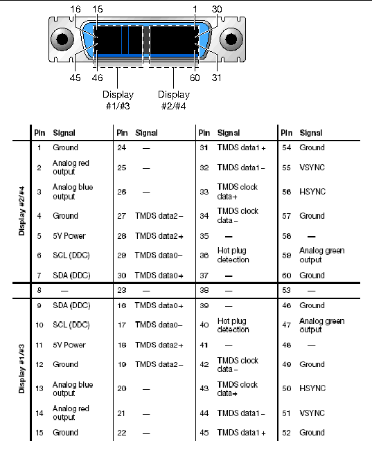
FIGURE C-1 shows the Sun XVR-200 LFH60 video connector and pin signal locations.
FIGURE C-1 LFH60 Connector and Pin Signal Descriptions

DVI Connector Pinouts
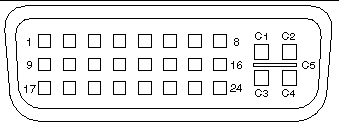
FIGURE C-2 and TABLE C-2 shows the DVI connector and pinout signals. The DVI cable connector is a 30-pin connector for a supported workstation monitor.
FIGURE C-2 DVI Connector Pinouts

TABLE C-2 Sun XVR-200 Graphics Accelerator DVI Cable Pinouts
|
Pin
|
Signal
|
|
1
|
TMDS Data 2-
|
|
2
|
TMDS Data 2+
|
|
3
|
TMDS Data 2/4 Shield
|
|
4
|
TMDS Data 4-
|
|
5
|
TMDS Data 4+
|
|
6
|
DDC Clock
|
|
7
|
DDC Data
|
|
8
|
Analog vertical sync
|
|
9
|
TMDS Data 1-
|
|
10
|
TMDS Data 1+
|
|
11
|
TMDS Data 1/3 shield
|
|
12
|
TMDS Data 3-
|
|
13
|
TMDS Data 3+
|
|
14
|
+5V power
|
|
15
|
Ground
|
|
16
|
Hot plug detect
|
|
17
|
TMDS Data 0-
|
|
18
|
TMDS Data 0+
|
|
19
|
TMDS Data 0/5 shield
|
|
20
|
TMDS Data 5-
|
|
21
|
TMDS Data 5+
|
|
22
|
TMDS Clock shield
|
|
23
|
TMDS Clock+
|
|
24
|
TMDS Clock-
|
|
C1
|
Red analog
|
|
C2
|
Green analog
|
|
C3
|
Blue analog
|
|
C4
|
Analog horizontal sync
|
|
C5
|
Analog ground
|
HD15 (VGA) Connector Pinouts
FIGURE C-3 and TABLE C-3 shows the HD15 (VGA) connector and pinout signals.
FIGURE C-3 HD15 (VGA) Connector Pinouts

TABLE C-3 Sun XVR-200 Graphics Accelerator HD15 Connector Pinouts
|
Pin
|
Signal
|
|
1
|
Red analog video
|
|
2
|
Green analog video
|
|
3
|
Blue analog video
|
|
4
|
Monitor ID2
|
|
5
|
Ground
|
|
6
|
Red shield
|
|
7
|
Green shield
|
|
8
|
Blue shield
|
|
9
|
No connect
|
|
10
|
Sync RTN
|
|
11
|
Monitor ID0
|
|
12
|
Monitor ID1 or DDC data
|
|
13
|
Horizontal sync
|
|
14
|
Vertical sync
|
|
15
|
Monitor ID3 or DDC clock
|
| Sun XVR-200 Graphics Accelerator Installation Guide
|
819-5737-11
|
   
|
Copyright © 2006, Sun Microsystems, Inc. All Rights Reserved.


