| C H A P T E R 4 |
|
Maintaining the Workstation |
This chapter provides instructions on how to add, replace and configure the components in the workstation after it is set up. The following sections are included in this chapter:
Before removing the system's left-side access panel, read the following sections. These sections contain important ESD precautions, along with preinstallation and postinstallation instructions.
Electrostatic discharge (ESD) can damage your processor, disk drives, expansion boards, and other components. Always observe the following precautions before you install a system component:
Always perform the following steps before you install any component:
1. Turn off the system and all of the peripherals connected to it.
2. Turn off the power button on the back of the chassis and leave the AC power cord plugged in.

|
Caution - Failure to properly turn off the system before you start installing components can cause serious component damage. |

|
Caution - Follow the ESD precautions described in Section 4.2.1, ESD Precautionswhen handling a system component. |
See Section 4.3, Opening the Workstation, for the appropriate procedure for opening the workstation.
Perform the following steps after installing a workstation component:
1. Ensure that all of the components are installed as described in the step-by-step instructions.
See Section 4.5, Component Replacement Procedures.
2. Reinstall any PCI cards or peripherals that you had previously removed.
See Section 4.5, Component Replacement Procedures.
3. Reinstall the system's left-side panel and front bezel.
See Section 4.3, Opening the Workstation.
4. Connect all external cables to the system.
See Section 1.4.1, Powering On the Workstation.

|
Caution - If the left-side panel and hard disk drives were removed, do not operate the workstation for more than ten minutes. Improper cooling airflow might damage the system's components. |

|
Caution - Before you proceed, turn off your system and all of the peripherals connected to it. Refer to Section 4.2.2, Preinstallation Instructions. |
You must remove the left-side access panel to gain access to the system's internal components.
1. Turn off the system and all of the peripherals connected to it.
2. Loosen the two captive thumbscrews located on the edge of the left-side panel closest to the back panel.
3. Slide the panel toward the back of the workstation. Tilt the top edge of the panel out and then up to remove it from the chassis.
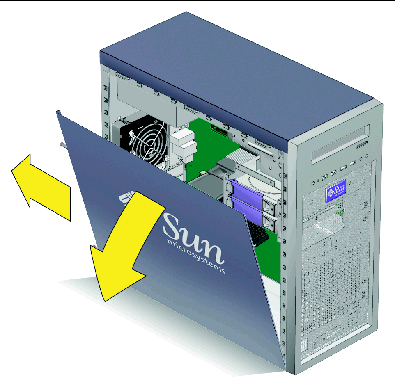
1. Remove the left-side access panel.
2. Loosen the four bezel tabs (see FIGURE 4-2).
Facing the left-front side of the bezel and starting with the topmost tab, carefully push each bezel-mounting tab about a millimeter and forward slightly.
As you do this, you can see the edge of the bezel nearest the tab move slightly away from the front of the chassis.

|
Caution - Be very careful when pulling the bezel away from the chassis. Applying too much force might cause the bezel to break. |
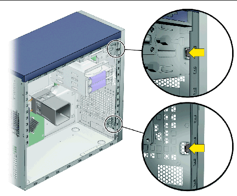
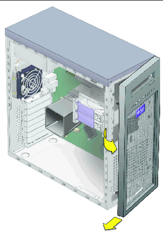
a. Move the left-front side of the bezel slightly forward, disengaging the left-side tabs from the chassis.
b. Gently shift the bezel to the left, releasing it from the right-front chassis hooks and the chassis (see FIGURE 4-3).
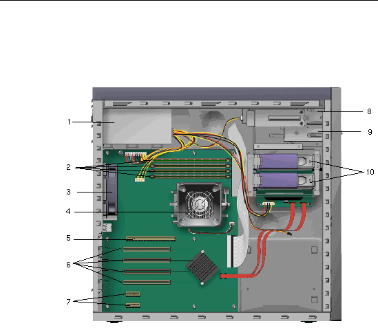
See FIGURE 4-4 to locate components before performing the remove and replace procedures.
|
Hard disk drives (HDD 1 is the top drive, HDD 2 is the bottom drive) |
The following sections contain instructions for components that can be replaced by customers and field service personnel.
The following procedures are for replacing customer-replaceable units (CRUs):
The following procedures should only be performed by trained field service technicians:
|
Note - The Sun Ultra 20 Workstation can accommodate up to two hard drives. If you are not removing an existing drive, proceed to Section 4.5.1.2, Installing a Hard Disk Drive. |
1. Turn off the power button on the back panel and open the chassis.
2. Locate the hard drive to be removed.
3. Unlock the hard drive handle by pushing the button to the right until the handle pops out (see FIGURE 4-5).
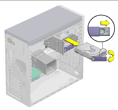
4. Disconnect the hard drive from the hard drive assembly by pulling the hard drive by the handle.
5. Set the hard drive aside on an antistatic mat.
1. Turn off the power button on the back panel and open the chassis.
2. Remove the hard drive from its antistatic packaging.
3. Push the handle release button to the right until the hard drive handle pops open.
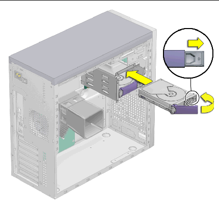
4. Locate the hard drive assembly and hard drive assembly guides.
If you are installing a second hard drive, install it in the remaining free slot in the hard drive assembly. The boot hard drive must be installed in hard drive slot HDD1 (top). The second hard drive bay is hard drive slot HDD2 (bottom).
5. Align the hard drive with the hard drive assembly guides and slide the hard drive into the hard drive assembly until the hard drive handle begins to close.
6. Press the hard drive handle closed until it locks the hard drive in the hard drive assembly.
This seats the hard drive connector into the SATA backplane connector.
7. Inspect the hard drive and related component fasteners to verify the following:
8. Replace the left-side access panel.
The SATA backplane is located behind the hard drive cage. The SATA backplane, the hard drives, and the hard drive bracket are collectively the hard drive assembly.
The hard drive assembly is installed in the hard drive bay. The hard drive power and interface cables connect to the hard drives through the SATA backplane.
This section describes removal and installation of the SATA backplane. Topics include:
1. Turn off the power button on the back panel open the chassis, and locate the SATA backplane (see FIGURE 4-7).
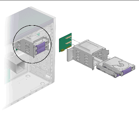
2. Remove all installed hard drives.
See Section 4.5.1.1, Removing a Hard Disk Drive.
3. Set the hard drive(s) on an antistatic mat.
4. Disconnect the cables (see FIGURE 4-8).
a. Disconnect the power cable from the SATA backplane.
b. Disconnect the SATA data cables from the SATA backplane.
c. Temporarily mark the cables to ensure proper orientation when replacing the part.
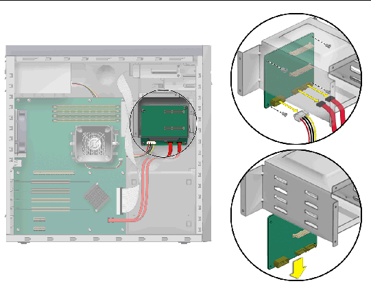
5. Unfasten the SATA backplane from the chassis (see FIGURE 4-8).
Using a No. 2 Phillips screwdriver, remove the four screws that secure the SATA backplane to the chassis. Set the screws aside in a container.
6. Slide the SATA backplane out of the hard drive bracket and set it aside.
7. Proceed to Section 4.5.2.2, Installing the SATA Backplane to install the new SATA backplane.
To install the SATA backplane:
2. Remove the new SATA backplane from its packaging.
3. Slide the SATA backplane under the hard drive bracket.
Position the screw holes over the holes in the chassis.
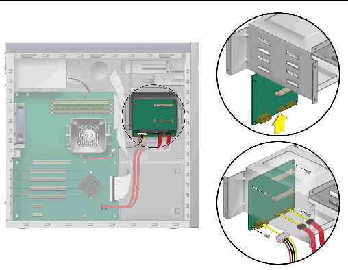
4. Fasten the SATA backplane to the hard drive bracket.
Using a No. 2 Phillips screwdriver, install the four screws that secure the SATA backplane to the hard drive bracket. Torque the screws to inch pounds.
5. Connect and route the cables (see FIGURE 4-9).
a. Connect the SATA interface cables to the SATA backplane connector.
b. Connect the power supply power cable to connector P4.
Refer to the cabling diagram in the service label on the side of the chassis for information on cable routing.
6. Slide the hard drive bracket into the hard drive bay until the latch clicks.
You are finished replacing the SATA backplane.
7. Install all hard drives into the hard drive bracket.
See Section 4.5.1.2, Installing a Hard Disk Drive.
8. Inspect the SATA backplane and the related component fasteners.
9. Inspect the SATA backplane and the related component cabling.
10. Replace the left-side panel of the workstation.
1. Remove any media in the DVD drive.
2. Turn off the power button on the back of the system and power off all of the peripherals connected to the workstation.
3. Remove the left-side access panel.
4. Remove the front bezel (see Section 4.3.2, Removing the Front Bezel).
5. Disconnect the cables from the back of the DVD drive.
6. Push the drive retaining lever tab up to release the lever from its retaining hooks (see FIGURE 4-10).
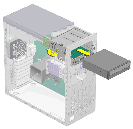
7. Gently pull out the DVD drive from the front of the chassis.
8. Place the DVD drive on a static-dissipating work surface or inside an anti-static bag.
9. Install the new DVD drive as shown in Section 4.5.3.2, Installing a DVD Drive.
1. Remove the DVD drive from its packaging.
2. Turn off the power button on the back panel and all of the peripherals connected to the workstation.
3. Remove the left-side access panel.
4. Slide the 5.25-inch drive with preinstalled carrier into the drive bay.
Ensure that the holes in the drive case are aligned with the holes in the chassis drive bay, from which the drive retaining lever pin was withdrawn.
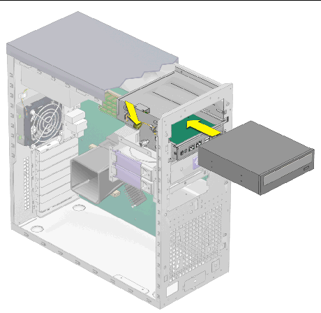
5. Lock the drive in the bay by rotating the drive retaining lever downward until the drive is captured by the retaining hooks.
6. Connect the IDE, power, and jumper cables to the back of the DVD drive (see FIGURE 4-12).
Refer to the cabling diagram in the service label on the side of the chassis for information on correct cable routing.
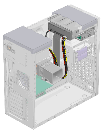
7. Replace the front bezel and left-side cover of the workstation.
This section contains instructions for removing and installing a dual inline memory module (DIMM).

|
Caution - Before removing any DIMMs from the motherboard, create a backup file to preserve any important data. |
To determine which DIMM modules are not functioning properly so that they can be replaced:
1. Boot the machine with the supplemental CD in the disk drive.
2. Run the PC-Check diagnostic tool that comes with the supplemental CD.
3. Choose option 1, hardware diagnostic tests.
4. Select advanced diagnostic tests; then select memory.
This shows all the system memory.
5. Ensure that all the memory tests are selected by selecting test set in the memory test menu.
All tests should be highlighted in yellow, with a dot to the left of each.
6. Exit the screen by pressing the Esc key.
This begins testing all the memory in the system. If a DIMM module is faulty, PC-Check indicates which one failed and highlights it in red.
8. Make a note of any failed DIMM modules.
9. Shut down the machine and switch off the AC power from the back.
10. To remove the faulty module and replace it with a new one, continue to Section 4.5.4.2, Removing a DIMM.
1. Turn off the power button on the back panel and all of the peripherals connected to the workstation.
2. Remove the left-side access panel.
3. Gently lay the system on its right side on a stable, nonslip surface.
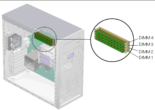
4. Identify the location from which you will remove a DIMM (see FIGURE 4-13).
5. Place your forefingers on the top of the DIMM.
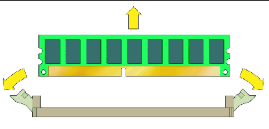
6. Remove the DIMM by pressing down on the ejector bars at both ends of the DIMM socket (FIGURE 4-14).
7. Set the DIMM aside on an antistatic mat.
8. Install a new DIMM as shown in Section 4.5.4.3, Installing a DIMM.
When you install a DIMM in the workstation, keep the following guidelines in mind:
|
Note - An exception to this guideline is when a DIMM module fails and becomes replaced with a unit shipped from Sun Microsystems. In that case, the DIMM modules may be replaced individually. |
1. Turn off the power button on the back panel and all of the peripherals connected to the workstation.
2. Remove the left-side access panel.
3. Gently lay the system on its right side on a stable, nonslip surface.
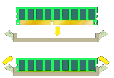
5. Align the DIMM with the proper slot.
6. Insert the DIMM into the slot.
Using both thumbs, press the DIMM straight down into the DIMM slot until both ejector levers click, locking the DIMM in the DIMM slot.
7. Repeat Step 4 through Step 6 for each DIMM that you want to replace.
8. Replace the left-side access panel.
The system automatically detects the amount of memory installed. Run the BIOS setup to view the new value for total system memory, and make a note of it.
This procedure describes how to install a typical PCI card (including the host bus adapter) or graphics card. PCI and graphics cards might vary in the way in they are installed in the system.
If you are adding a new card and not replacing a PCI or graphics card, go to Section 4.5.5.2, Installing a PCI or Graphics Card.
To remove a PCI or graphics card:
1. Turn off the system and all of the peripherals connected to it, then unplug the AC power cord from the system.
2. Remove the left-side access panel.
3. Gently lay the system on its right side on a stable, nonslip surface.
4. Remove any cables connected to the card.
5. Follow the instructions for the type of card you are removing:
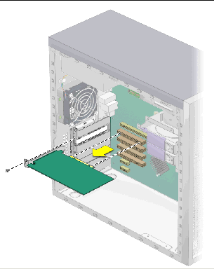
a. Unscrew the PCI card retainer.
Gently rock the PCI card forward, and then lift it straight out of the PCI card slot and set it aside on an antistatic mat.
a. If you are removing a NVIDIA FX3450 card, remove the power supply PCI cable from the power connector on the FX3450 card.
b. Unfasten and open the PCI card retainer.
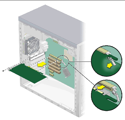
c. Pull the latch that secures the card to the slot away from the card.
Gently rock the card forward, and then lift it straight out of the graphics card slot and set it aside on an antistatic mat.
Note the following if you are installing 33 Mhz PCI cards (see FIGURE 4-18 and TABLE 4-2):
|
Note - Any 64-bit PCI cards that you install will run in 32-bit mode. |
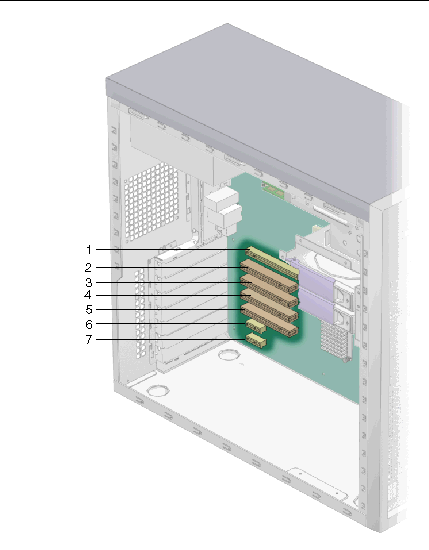
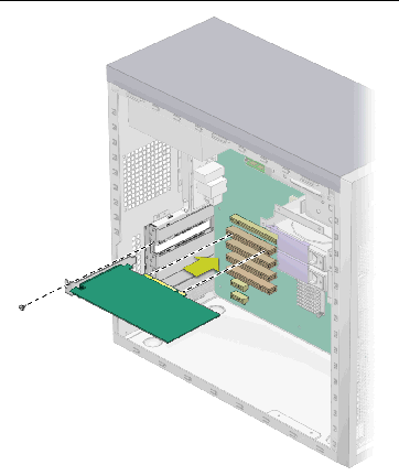
To install a PCI or graphics card:
1. Turn off the power switch on the back of the system and the power to all of the peripherals connected to the system.
2. Remove the left-side access panel.
3. Gently lay the system on its right side on a stable, nonslip surface.
4. Refer to the service label, attached to the inside of the access panel, to help you choose an empty card slot that is compatible with the card that you are installing.
6. Remove the PCI or graphics card from its protective packaging, and lay the card on an antistatic surface until you are ready to install it.
7. Follow the instructions for the type of card you are installing:
a. Position the card over the selected slot.
b. Press down on the card until it is completely seated in the slot.
a. Pull the tab at the right side of the slot away from the slot.
b. Position the card in the selected slot. Ensure that the notch, on the bottom right corner of the card, engages the latch on the motherboard.
c. Press down on the card until it is completely seated in the slot.
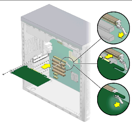
8. Fasten the retaining screw into place. Torque the screws to 8- to 9-inch pounds.
9. If you are installing a NVIDIA FX3450 card, attach the power supply PCI cable to the power connector on the FX3450 card.
10. Replace the left-side access panel.
The battery specifications for the Sun Ultra 20 Workstation are shown in TABLE 4-3.
To remove and install the battery:

|
Caution - If you remove the system battery, you could erase all system-specific information saved in the CMOS. |
1. Turn off the power button on the back panel and all of the peripherals connected to the workstation.
2. Remove the left-side access panel.
3. Gently lay the system on its right side on a stable, nonslip surface.
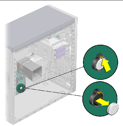
4. Pinch the battery latch together until the battery pops out of the motherboard socket (see FIGURE 4-21).
5. Lift the battery to remove it (see FIGURE 4-21).
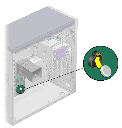
6. Insert a new battery with the positive sign (+) facing up (see FIGURE 4-22).
Tilt the battery into the battery connector, angling the battery under the battery latch. Slide the battery until it clicks into place.
7. Replace the left-side access panel.
1. Turn off the power button on the back panel and all of the peripherals connected to the workstation.
2. Remove the left-side access panel.
3. Locate the system fan on the back inside panel of the workstation.
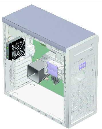
4. Disconnect the system fan's power connector from the Fan 1 connector on the motherboard.
5. Push forward the two latches on the left side of the fan bracket, and pull the fan to the left to release the four hooks on the back of the bracket from the holes in the chassis (see FIGURE 4-24).
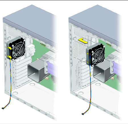
6. Pull the fan away from the chassis.
1. Remove the left-side access panel, if necessary.
2. Remove the new fan from its package.
3. Locate the four corner holes in the chassis grill where the fan tabs will be installed.
4. Push forward the two latches on the left side of the fan bracket, and attach the four hooks on the back of the bracket to the four corner holes in the back chassis grill (see FIGURE 4-25).
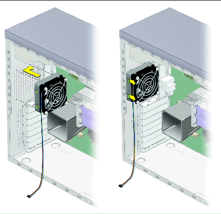
5. Release the latches on the left of the fan after the fan is secured to the chassis.
6. Connect the fan cable to the Fan 1 connector on the motherboard.
Refer to FIGURE 4-34 or the service label on the system cover for the location of the Fan 1 connector.
1. Turn off the power button on the back panel and all of the peripherals connected to the workstation, and then unplug the AC power cord from the system.
2. Remove the left-side access panel.
3. Gently lay the system on its right side on a stable, nonslip surface, and locate the power supply (see FIGURE 4-26).
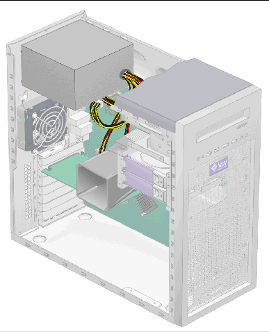
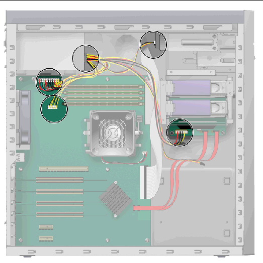
4. Unfasten the connectors from the motherboard and release the cable management strap (see FIGURE 4-27).
5. Unfasten the power connectors attached to the motherboard, DVD drive and SATA backplane (see FIGURE 4-27 and TABLE 4-4).
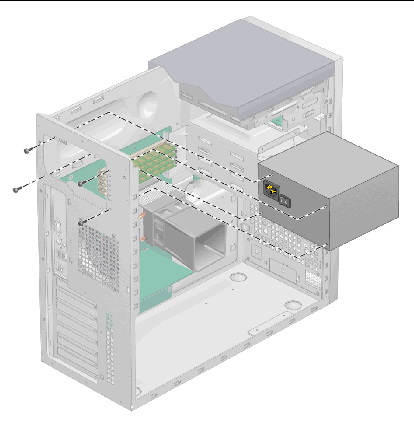
6. Working from outside the back of the chassis, unfasten the four mounting screws and withdraw the power supply through the interior of the system chassis (see FIGURE 4-28).
7. Install the new power supply as shown as Section 4.5.8.2, Installing the Power Supply.
1. Remove the left-side access panel, if necessary.
2. Gently lay the system on its right side on a stable, non-slip surface.
3. Remove the new power supply from its package.
4. Locate where the power supply is to be installed, and place the power supply inside the chassis (see FIGURE 4-29).
a. Align the power supply IEC-320 connector (power cord socket) and fan with the chassis back-panel opening.
b. Position the power supply with the chassis power supply brackets.
c. Rotate the power supply down and into the chassis.
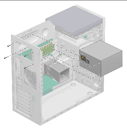
5. Fasten the power supply to the chassis.
6. Reconnect the power supply cables (see FIGURE 4-27 and TABLE 4-4) and secure them with the cable management tie.
7. Replace the left-side access panel.
To remove the I/O board assembly:
1. Turn off the power button on the back panel and all of the peripherals connected to the workstation.
2. Disconnect any audio, USB, and IEEE 1394 cables connected to the front of the workstation.
3. Remove the bezel (see Section 4.3.2, Removing the Front Bezel).
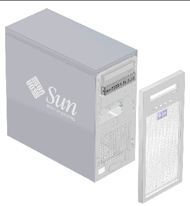
4. Remove the left-side access panel and locate the back of I/O board assembly.
5. Disconnect all cables on the back of the I/O board.
6. Loosen the captive screw securing the I/O board to the metal frame (see FIGURE 4-31).
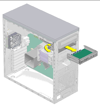
7. Push the I/O board out the front of the chassis.
8. Install the new I/O board assembly as shown in Section 4.5.9.2, Installing the I/O Board Assembly.
To install the I/O board assembly:
1. Turn off the power button on the back panel and all of the peripherals connected to the workstation.
2. Place the system unit on a flat, stable surface.
3. Push the I/O board through the back of the metal I/O board frame until the front panel is flush with the bezel opening (see FIGURE 4-32).
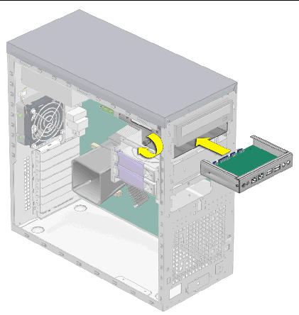
4. Tighten the captive screw on the metal I/O board frame to secure the I/O board.
5. Connect the internal USB, Power/LED, FireWire, and audio cables to the back of the I/O board.
See FIGURE 4-33 and FIGURE 4-34 and the service label on the chassis cover for the locations of the I/O board connections.
6. Replace the left-side access panel.
7. Connect cables to the front-panel connectors as necessary.
|
Note - These connectors are not keyed. Make sure that you reinstall them in the proper orientation. Be careful not to bend the pins. |
The following system cables have a connector at each end, and so can be removed or installed by the customer. All other cables are permanently attached to a system component at one end and must be removed or replaced along with the component. See FIGURE 4-33 for locations of connectors.
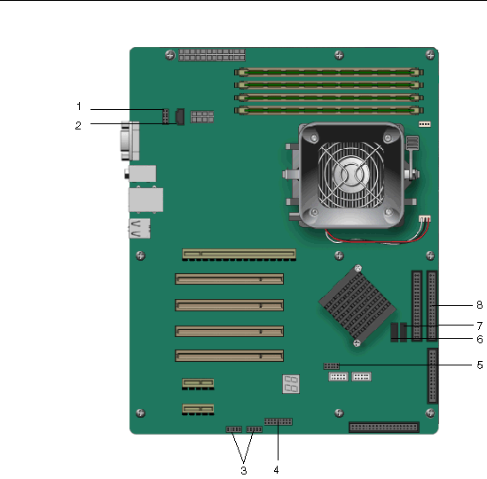
Each cable connector on the motherboard is labeled to help you identify the cable to which it should be connected.
To remove and install system cables:
1. Turn off the power button on the back panel and all of the peripherals connected to the workstation.
2. Remove the left-side access panel.
3. Gently lay the system on its right side on a stable, nonslip surface.
4. Replace any cables that need to be replaced (see FIGURE 4-34).
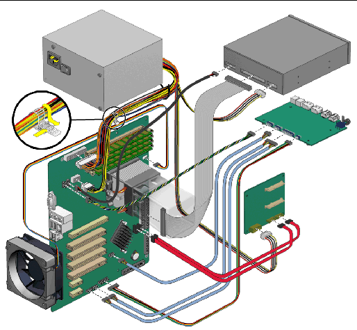
5. Ensure that all cable routing is correct, and that all of the cable connectors are properly seated, before reinstalling the left-side access panel.
This section describes how to remove or replace a CPU and heatsink.
|
Note - The CPU is not a CRU and should be replaced only by trained field service technicians. The exception is the AMD Opteron model 180. See the following section for details. |
If you are installing an AMD Opteron model 180 CPU, you must use the heatsink/fan assembly that is included with the model 180 CPU.
The model 180 processor can be installed without a field service technician present. Make sure to carefully follow this installation procedure to avoid damaging the processor
You will note that the heatsink/fan assembly that is included with the CPU looks different than the assembly depicted in the remove and install procedures (see FIGURE 4-35). Otherwise, the procedure for installing the CPU and heatsink/fan assembly is the same as the procedure in the following sections.

|
Caution - Failure to use the supplied heatsink for the Opteron 180 will cause insufficient cooling, leading to premature failure of the processor. |
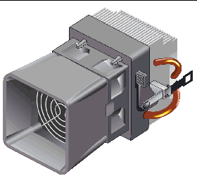
|
Note - Before removing a CPU from the motherboard, create a backup file to preserve all important data. |
1. Turn off the power button on the back panel and all of the peripherals connected to the workstation.
3. Remove the left-side access panel.
4. Gently lay the system on its right side on a stable, nonslip surface.

|
Caution - The heatsink can become extremely hot. Allow a few minutes for the heatsink to cool before attempting this procedure. |
5. Disconnect the CPU fan cable from its connector on the motherboard.
6. Pull up the black lever on the right side of the heatsink/fan assembly to loosen the metal latch from the hook on the retaining bracket (see FIGURE 4-36).
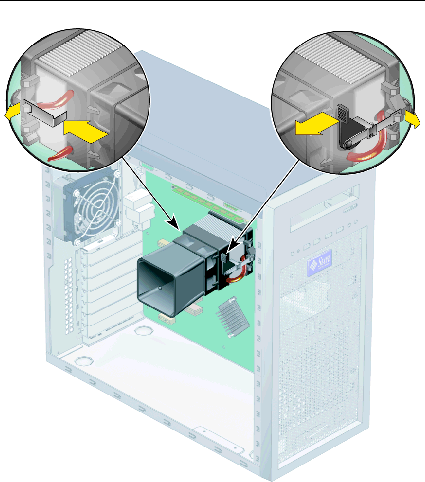
7. Push down the metal latch on the left side of the assembly to loosen the latch from the hook on the retaining bracket (see FIGURE 4-36).
8. Twist the heatsink/fan assembly to the right or the left, in order to break the seal with the thermal grease.
9. Lift the heatsink/fan assembly straight up and withdraw it from the board (see FIGURE 4-37).
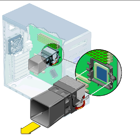
10. Place the heatsink upside down on a flat surface to prevent the thermal grease from contaminating other components.
11. Depress, and then pull up the CPU socket retainer lever up to the fully open, perpendicular position (see FIGURE 4-38).
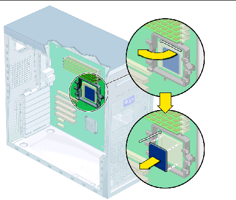
12. Lift the CPU out of the socket, leaving the retainer lever in the open position.
13. Install the heatsink and CPU as shown in Section 4.5.11.3, Installing a Heatsink and CPU.
To install a heatsink and CPU:
|
Note - Observe the ESD precautions and preinstallation procedures described in Section 4.2.1, ESD Precautions. |
1. Ensure that the CPU socket retainer lever is in the fully open, upright position.
2. Align the CPU to its socket so that pin 1 of the CPU (indicated by the notched corner) is aligned with hole 1 of the socket (indicated by the arrow in the corner of the socket).
3. Insert the CPU into the socket.
|
Note - When correctly aligned, the CPU should drop effortlessly into the socket. Do not attempt to force the CPU into the socket to seat it. |
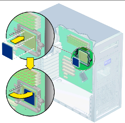
4. When the CPU is positioned in the socket, press down on the socket retainer lever to lock the CPU in place.
a. Clean any contamination from the top of surface of the CPU, using the supplied alcohol wipe.
The heatsink assembly already has thermal grease applied. You do not need to apply additional thermal grease.
b. Remove the plastic cover from the heatsink/fan assembly.
a. Remove the grease from the CPU and remove the thermal interface material from the heatsink using the alcohol wipe supplied with the motherboard.
b. Use the syringe that is supplied with the motherboard to apply approximately 0.5 ml of thermal grease to the center of the top of the CPU.
Empty the entire syringe onto the chip.
c. Using the wrapper of the alcohol wipe or a finger inserted into a clean plastic bag, spread out the thermal grease to a thin uniform thickness over the CPU.

|
Caution - Do not use an unprotected finger to spread the thermal grease, as the oils on your finger will degrade the performance. |
6. Inspect the heatsink/fan assembly for dust and lint. Clean if necessary.
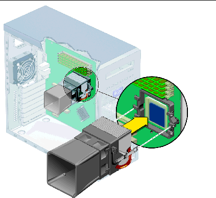
7. Carefully position the heatsink/fan assembly on the CPU, aligning it with the mounting hooks to reduce movement after it makes initial contact with the layer of thermal grease.

|
Caution - If the heatsink assembly is moved too much during its installation, the layer of thermal grease might not be distributed evenly, leading to component damage. |
8. Attach the retaining bracket hook to the metal latch on the left side of the heatsink/fan assembly.
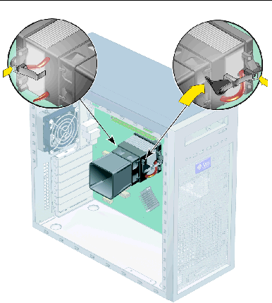
9. Push down on the black lever on the right side of the heatsink/fan assembly to secure the metal latch to the hook on the retaining bracket.
10. Connect the CPU fan cable to the connector on the motherboard.
11. Replace the left-side access panel.
The following sections describe how to remove and install the Sun Ultra 20 Workstation system motherboard.
|
Note - The motherboard is not a CRU and should only be replaced by trained field service technicians. |
1. Turn off the power button on the back panel and all of the peripherals connected to the workstation.
2. Remove the left-side access panel.
3. Gently lay the system on its right side on a stable, nonslip surface.
4. Remove any PCI cards installed on the motherboard (see Section 4.5.5, Replacing a PCI or Graphics Card).
5. Disconnect all cables attached to the motherboard.
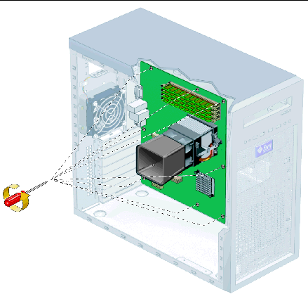
6. Remove the eight Phillips screws that fasten the motherboard to the chassis (see FIGURE 4-42).
|
Note - Do not remove the four screws that secure the CPU heatsink/fan assembly mounting to the motherboard. |
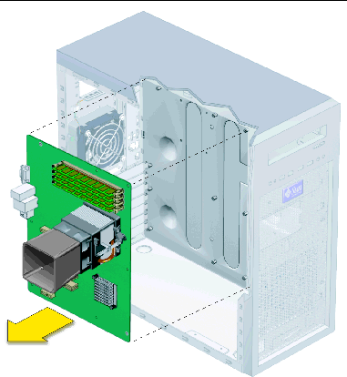
7. Pull the motherboard away from the chassis (see FIGURE 4-43).
Refer to the following sections to remove and replace the CPU and memory:

|
Caution - Observe proper ESD precautions when handling the new motherboard. |
1. Replace the CPU or DIMMs as necessary.
Refer to the following sections for information about removing and replacing the CPU and memory:
2. Center the motherboard on the chassis so that the screw holes in the motherboard align with the screw holes on the chassis.
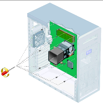
3. Secure the eight Phillips screws that fasten the motherboard to the chassis. Torque the screws to 8- to 9-inch pounds (see FIGURE 4-44).
4. Replace any PCI or graphics cards.
See Section 4.5.5, Replacing a PCI or Graphics Card.
5. Reconnect all internal system cables.
See Section 4.5.10, Replacing System Cables.
7. Replace any external cables, and power on the workstation.
Copyright © 2006, Sun Microsystems, Inc. All Rights Reserved.