| Skip Navigation Links | |
| Exit Print View | |

|
Sun Fire X4800 Server Product Documentation |
Attaching Administration (SP) Cables
Powering the Server On and Off
How to Apply Standby Power for Initial Service Processor Configuration
How to Power On All Server Components
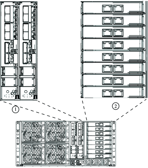
For 4P systems connect cables only to slots 0 and 3.
4P systems contain CPU modules in slots 0 and 3, and filler panels in slots 1 and 2.
For 8P systems, connect cables to slots 0, 1, 2 and 3.
8P systems contain CPU modules in all four slots.
See your PCIe EM documentation for details.
4P systems support PCIe EMs in slots 0.0, 0.1, 3.0 and 3.1 (the top two and bottom two).
8P systems support PCIe EMs in slots 0.0, 0.1, 1.0, 1.1, 2.0, 2.1, 3.0 and 3.1 (all slots).

| ||||||