| Skip Navigation Links | |
| Exit Print View | |

|
Sun Fire X4800 Server Product Documentation |
Administration, Diagnostics, and Service
Sun Fire X4800 Server Service Manual Overview
Sun Fire X4800 Server Overview
Sun Fire X4800 Server Chassis Overview
Sun Fire X4800 Server CPU Module (CMOD) and Filler Module Overview
Sun Fire X4800 Server Subassembly Module Overview
Front Panel Indicator Module Overview
Hard Drive and XL Bracket Assembly Overview
RAID Expansion Module Overview
Fabric Expansion Module Overview
CPU and Heatsink Assembly Overview
Network Express Module Overview
Service Processor (SP) Module Overview
SP Module Multi Port Cable Overview
Fan Module Controller Board (FB) Overview
Controlling Server Power Remotely
How to Use the ILOM Command-Line Interface to Control Power
How to Use the ILOM Web Interface to Control Power
How to Use IPMItool to Control Power
Removing and Installing Components
Preparing for Service and Operation
Antistatic Precautions and Procedures
Removal and Installation Procedures
Removing and Installing a Power Supply (CRU)
How to Remove and Install AC Power Cables
Removing and Installing a Hard Drive (CRU)
Removing and Installing a Hard Drive Filler
How to Remove a Hard Drive Filler
How to Install a Hard Drive Filler
Replacing the Hard Drive Backplane (FRU)
How to Remove the Hard Drive Backplane
Hard Drive Backplane Cable Routing and Designations
How to Install the Hard Drive Backplane
Adding, Removing, and Installing a CMOD (CRU)
How to Add a CPU Module (CMOD) to the Server Using the Upgrade Kit
How to Remove a CPU Module (CMOD)
How to Remove the CPU Module (CMOD) Cover
How to Install the CPU Module (CMOD) Cover
How to Install a CPU Module (CMOD)
CPU Module (CMOD) Designation and Population Rules
CPU Module (CMOD) Designations
CPU Module (CMOD) Population Rules
Removing and Installing a CMOD Filler
How to Replace the CMOD Battery (CRU)
Removing and Installing DIMMs (CRU)
Removing and Installing a RAID Expansion Module (CRU)
How to Remove a RAID Expansion Module
How to Install a RAID Expansion Module
How to Replace the RAID Expansion Module Battery (CRU)
Removing and Installing a Fabric Expansion Module (CRU)
How to Remove a Fabric Expansion Module
How to Install a Fabric Expansion Module
Replacing a CPU and Heatsink Assembly (FRU)
How to Remove a CPU and Heatsink Assembly (FRU)
How to Install a CPU and Heatsink Assembly (FRU)
Removing and Installing a Fan Module (CRU)
Replacing a Fan Module Controller Board (FRU)
Fan Module Controller Board (FB) Designations
How to Remove a Fan Module Controller Board
How to Install a Fan Module Controller Board
Removing and Installing a NEM or a NEM Filler (CRU)
Network Express Module Designations and Assignments
How to Remove a NEM or a NEM Filler
How to Install a NEM or a NEM Filler
Removing and Installing a PCIe EM (CRU)
PCIe EM Designations and Population Rules
How to Install a PCIe EM or PCIe EM Filler
Removing and Installing the Service Processor Module (CRU)
Removing and Installing the Multi port Cable
How to Remove the Multi Port Cable
How to Install the Multi Port Cable
Removing and Installing the Subassembly Module (FRU)
How to Install the Subassembly Module
Sun Fire X4800 Server Service Procedures, and Information
How to Backup Motherboard FRUID Information
How to Restore Motherboard FRUID Information
How to Update Motherboard FRUID Information
Firmware Information and Procedures
How to Use the Tools and Drivers CD
SP Module and CMOD Firmware Compatibility Considerations
How to Access the BIOS Setup Utility
How to Update the CPLD From Oracle SunService
How to Update the CPLD From Service Mode
Component LED Locations and Meanings
Front Panel Power Supply LED's
Back Panel Network Express Module LED's
Before You Begin
Review the following topics:
The AC power connectors are retained by a wire latch. Lift the retaining latch and pull the connector out of its socket (see AC Power Block Overview).
Partially remove the power supplies. This action ensures that the power supplies are disconnected from the midplane connectors.
CMODs and CPU filler modules must be returned to their original slots. For CMOD slot designations, see CPU Module (CMOD) Designations.
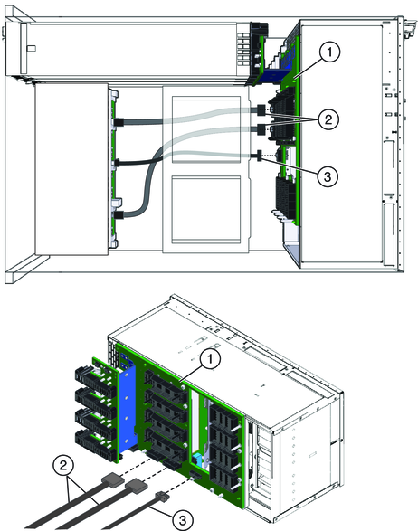
Note - Do not disconnect the cables from the hard drive backplane.

Note - Do not disconnect the cables at the hard drive backplane.
If you are not replacing the SAM, removal of this component is optional but recommended.
If you are not replacing the SAM, removal of this component is optional but recommended.
If you are not replacing the SAM, removal of this component is optional but recommended.
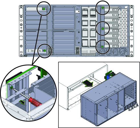
Two of the captive screws are accessible through the airflow vanes of Fan module bays FM 0 and FM 2. To access the screws lift open the top and bottom air flow vanes.

Next Steps