| C H A P T E R 1 |
|
Hardware Notes and Issues |
This chapter describes hardware issues related to the Sun Blade 6048 modular system. It includes the following issues:
This section describes items to note regarding hardware for the Sun Blade 6048 modular system.
The Sun Blade 6048 Modular System 2U Expansion Module is an option that can be installed on top of the 6048 modular system chassis to add additional 2U space. Components installed in the expansion module must weigh less than 100 lbs and provide front-to-back cooling.
The Expansion Module was designed primarily to support standard 19-inch networking switches. Refer to the server’s release notes for guidance as to whether or not a specific server is supported in the Expansion Module.
The Light Load Efficiency Mode (LLEM) is a new feature of CMM ILOM 3.0.6.11. To enable or disable LLEM, use the command:
set /CMM/policy/LIGHT_LOAD_EFFICIENCY_MODE=[enabled|disabled]
When LLEM is disabled, you can turn the PSU sides on or off with the command:
set /CMM/policy/MONITOR_PSx_SIDEy=[enabled|disabled]
| Note - It’s advisable to disable any PSU side first before unplugging the power cord. |
While enabled, LLEM runs in both redundant and non-redundant mode. Under the LLEM, CMM monitors the power being used and automatically shuts down the PSU sides to achieve higher efficiency.
You can check the sensor value of /CH/PSx/Sy/I_V12 or /CH/PSx/Sy/V_OUT_OK, where the value of I_V12 being 0 or V_OUT_OK deasserted indicates the corresponding side is disabled. CMM always disables PSU sides in descending order. When the power load level increases, CMM re-enables those disabled sides to cover the demand. If a new blade is inserted into the chassis, they can be powered on even if their power budget exceeds the power available from the sides currently turned on.
The redundant mode is set by the command:
set /CMM/powermgmt/redundancy=n+n
All MONITOR_PSx_SIDEy are set to enabled, and any attempt to disable any PSU side’s monitoring is not allowed. For example, the command set/CMM/policy/MONITOR_PSx_SIDEy=disabled will result in an error.
The non-redundant mode is set by the command:
set /CMM/powermgmt/redundancy=none
You can disable any PSU sides monitoring, for example, a side that doesn’t have a power cord.
In both redundant and non-redundant modes, LLEM works on those sides that are under monitoring.
When an unexpected AC fault happens, LLEM will be suspended and all sides will become enabled, verified by the sensor value of I_V12 and V_OUT_OK. If the fault is cleared, LLEM will automatically go back into effect.
When the LLEM is disabled, all PSU sides, including those previously disabled, become enabled. This can be verified by the sensor value of I_V12 and V_OUT_OK.
For detailed information on ILOM 3.0.6, see the ILOM Feature Updates and Release Notes.
An upgraded chassis and midplane upgrade kit are now available for the Sun Blade 6048 modular system.
The upgraded chassis is configured to enable installation of the Sun Cooling Door 5200 and 5600, and includes a PCIe 2.0-compliant midplane. The manufacturing part number for the upgraded chassis is 594-5971.
The midplane upgrade kit includes a PCIe 2.0 midplane that can be installed in the current chassis. The manufacturing part number for the upgraded midplane is 541-3542. For instructions on installing the midplane, see the Sun Blade 6048 Modular System Service Manual at:
http://docs.sun.com/app/docs/prod/blade.6048mod
Instructions on how to install the cooling doors are available in the documentation that is included with the door.
To determine which midplane you have installed in the chassis, check the FRU ID information through the ILOM CLI or Web interface.
See the Sun Integrated Lights Out Manager User’s Guide for more information on viewing component information.
1. Log in to the ILOM CLI as an Administrator or Operator.
2. At the command prompt, type:
The manufacturing part number will be displayed in the fru_part_number field.
1. Log in to the ILOM web interface as an Administrator or Operator.
2. Select System Information --> Components.
The Component Management page appears.
3. Click on /CH in the Component Management Status table.
A dialog box appears with information about the chassis.
The midplane manufacturing part number will be displayed in the fru_part_number field.
For information on server modules and storage modules (blades) that are supported by the Sun Blade 6048 modular system, refer the links for each server module at:
http://www.sun.com/servers/blades/6048chassis/
For information on PCIe ExpressModules (PCIe EMs) and PCIe Network Express Modules (NEMs) that are supported by the Sun Blade 6048 modular system, see:
http://www.sun.com/servers/blades/optioncards.jsp
You can also view documentation for these modules at:
Please read the following caution regarding door of the Sun Blade 6048 modular system cabinet:
Plug the cords for each power supply in the Sun Blade 6048 shelf into different power sources to provide redundant power for the system, in case one power source becomes unavailable.
This section describes hardware issues for the Sun Blade 6048 modular system.
When replacing a chassis midplane, follow the sequence listed below to avoid damage to the midplane. Refer to the Sun Blade 6048 Modular System Service Manual for detailed instructions on removing and installing a midplane.
To replace the chassis midplane:
1. Remove the chassis midplane.
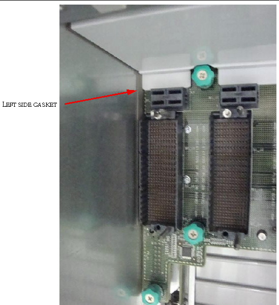
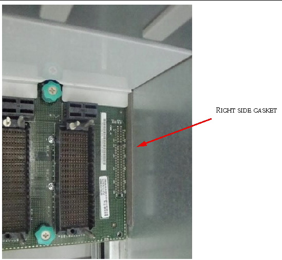
2. Pull off the gasketing material attached to the left and right sides of the chassis.
See FIGURE 1-1 and FIGURE 1-2 for the positions of the gasketing material in the chassis.
Do not re-install the gasketing material.

|
Caution - Thermal damage to the chassis can occur. Failure to remove the gasketing material prior to installing the midplane might result in damage to chassis. |
FIGURE 1-1 Position of Gasket on Left Side of the Chassis

FIGURE 1-2 Position of Gasket on Right Side of the Chassis

TABLE 1-1 shows the LED behavior for 10/100/1000 MB LEDs for Sun Blade 6048 network express modules (NEMs). The LED color can be different, depending on the server module that is using the Ethernet port.
| Note - See the chassis and NEM documentation for specifics on the connectors available for each NEM. |
The Sun Blade 6048 modular system contains two power supply modules that each have a power rating of 8400 W. Each power supply has three power connectors, with a 20A circuit per connector.
If you do not need the total power capacity of the power supplies, you have the alternative to use only two of the power connectors on the power supply. If you use only two power connectors, use the two to the right of each power supply (PS1-AC1, PS1-AC0 and PS0-AC1, PS0-AC0).
If you do use the two power connectors for a power supply, you will see IPMI SEL logs for missing AC connections in both CMM and server module SP log. Additionally, if the SNMP trap is configured, there SNMP traps will be sent out. The PSU Fault LED will be on. The DC-OK LED and the AC LED for the power supply will be off.
Further information on operating the power supplies with two connectors is available in Sun Blade 6048 Modular System Service Manual.
For a chassis that has A231 power supplies installed, the ILOM power meter feature is not currently available.
This could result in missing information in the ILOM CLI and web interface. The following readings will occur if the power supply current is < 25 Amps:
You will get the following output when you type the show command in CLI:
You can determine the amount of current a PSU side is drawing by reading the psX.I12V_Z sensor; where x=0..1 (PSU) and z=0..1 (PSU side) for A206 PSUs and x=0..1 (PSU) and z=0..3 (PSU side) for A231 PSU.
If using the CLI, you can determine the amount of current a PSU is drawing by typing:
Where x= 0..1. (PSU) and with A206 model PSUs, y = 0..1 (PSU side) and with A231 PSUs y = 0..2 (PSU side).
Copyright © 2009 Sun Microsystems, Inc. All rights reserved.