| C H A P T E R 2 |
|
Hardware Installation and Removal |
This chapter describes the tasks required to install and remove the NEM when the Sun Blade 8000 Modular System is in a powered-on state.
This chapter contains the following topics:

|
Caution - Damage to the NEM can occur as the result of careless handling or electrostatic discharge (ESD). Always handle the NEM with care to avoid damage to electrostatic sensitive components. |
To minimize the possibility of ESD-related damage, Sun strongly recommends using both a workstation antistatic mat and an ESD wrist strap. You can get an ESD wrist strap from any reputable electronics store or from Sun as part number #250-1007. Observe the following precautions to avoid ESD-related problems:
This section describes the process for installing a new Network Express Module (NEM) in a powered-on Sun Blade 8000 or Sun Blade 8000 P system.
The following sections describe these steps in more detail.
|
1. Attach an antistatic strap (refer to Observing ESD and Handling Precautions).
2. Refer to your system installation or service manual to determine an appropriate slot in which to install the NEM.
3. Unpack the NEM and remove it from the antistatic bag.
4. Locate a vacant NEM slot in the back of the chassis. Ensure the label on top of the NEM is facing up.
5. Align the NEM with the vacant slot.
Ensure that the NEM’s port connectors are facing toward you and that the NEM ejector levers are fully opened.
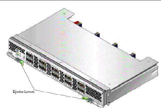
6. Align the NEM with the chassis guidance system and slide the NEM into its slot (see FIGURE 2-2).
Ensure that the NEM engages with the system chassis guidance system. Failure to align the NEM correctly can result in damage with the internal connection to the chassis midplane.
FIGURE 2-2 Inserting the NEM Into the Chassis
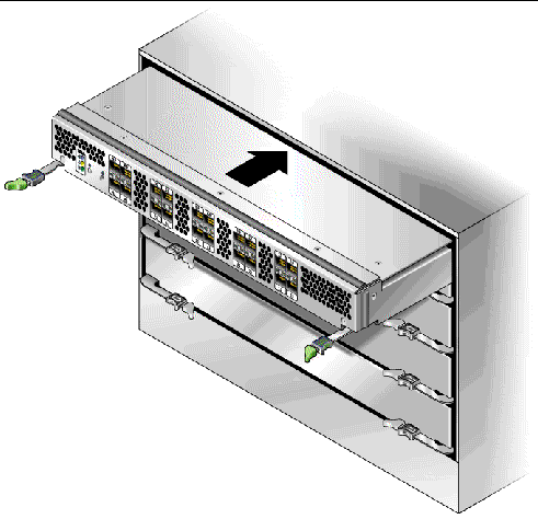
7. Push the ejector levers toward each other and close the levers to secure the NEM in its slot.
After you physically install the NEM in its slot, the Chassis Monitoring Module (CMM) will automatically detect the presence of the NEM. The OK LED goes to Standby blink (see TABLE 2-3 for LED status).
8. Press the Attention button to notify the blades (host operating systems) of the presence of the NEM.
9. Verify that the NEM is working properly.
See To Verify NEM Status.
|
| Note - The NEM does not allow normal data transmission on an optical link unless it is connected to another similar or compatible Fibre Channel (FC) product (that is, multimode to multimode). |
Use multimode fiber-optic cable, intended for short-wave lasers, that adheres to the specifications in TABLE 2-1.
Follow these steps when connecting the optical cables:
1. Connect each fiber-optic cable to an LC connector on the NEM (see FIGURE 2-3).
The ports are numbered 0-9 right-to-left as viewed from the back of the chassis. Each NIC has two external network ports. For each pair of external ports (for each blade), the top is port 0 and the bottom is port 1.
FIGURE 2-3 Connecting the Optical Cables
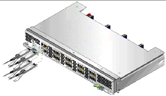
2. Connect the other end of each cable to a FC device.
After the optical cables are connected to the NEM, proceed to Configuring the NEM For Hot-Plug Operation.
3. Observe the light-emitting diodes (LEDs) status for the power-on self test (POST).
Each port has a corresponding set of LEDs that provide a visual indication of the operating state. See FIGURE 2-4 to determine the location of the port LEDs.
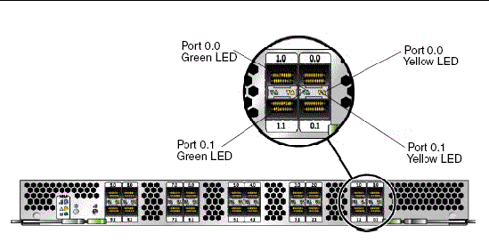
TABLE 2-2 summarizes port LED indicator combinations.
To insert a NEM into the chassis while the system is running, you need to:
1. Physically install the module.
2. Prepare the NEM for hot-insertion by using the CMM integrated lights-out management (ILOM) web interface or command-line-interface (CLI) and verify the NEM has returned the expected feedback.
See To Verify NEM Status.
3. Verify in one of the ILOM interfaces that the module’s Ready to Remove status is Not Ready.
1. Log in to the ILOM web interface using the IP address of the active Chassis Monitoring Module.
The first page of the ILOM web interface is displayed.
2. In the left navigation pane, select CMM.
The ILOM Version Information page is displayed.
3. Select the System Information tab, and then the Components tab.
The Component Management page is displayed. If you have installed a new NEM, go to Step 4.
When you were preparing a NEM for a hot-remove, if you selected Prepare to Remove from the Component Management page and corrected the problem without removing the NEM or if you decided not to remove the NEM, complete Step 3a and Step 3b.
a. Select the radio button next to the NEM that you want to hot-insert.
If you select the wrong NEM, click on the deselect icon at the top of the radio button column.
b. From the Actions drop-down list, select Return to Service.
When you select the Return to Service option, the system recognizes the inserted NEM, changes its Ready to Remove status to Not Ready, and lights the NEM’s green OK indicator.
4. Verify that the selected NEM has returned the expected feedback.
See To Verify NEM Status.
1. Log in to the ILOM CLI of the active Chassis Monitoring Module.
2. For a list of components in your system, type:
3. If you installed a new NEM, go to Step 4.
When you were preparing a NEM for a hot-remove, if you corrected the problem without removing the NEM or you decided not to remove the NEM, complete the following steps:
a. Type this command to prepare a component for a hot-insert:
set /CH/component return_to_service_action=true
set /CH/NEM1 return_to_service_action=true
b. Use the show /CH/component command to list the status of the connection from the NEM to each of the blades.
| Note - The following example depicts only the link status portion of the show /CH/component command output. |
c. If all blades that you expect to be connected show a Connected link status, go to Step 4. Otherwise, if a blade that you expect to be connected has a link status of Not connected, perform Step a - Step b again until its link status is Connected.
4. To verify that the NEM Ready to Remove status has changed to Not Ready, type:
show /CH/component prepare_to_remove_status
prepare_to_remove_status = Not Ready
5. Verify that the selected NEM has returned the expected feedback.
See the To Verify NEM Status.
You can replace many components in the chassis while the system is running by using a hot-plug procedure.
To insert modules into the chassis while the system is running, you need to:
1. Physically install the module.
2. Verify in one of the ILOM interfaces that the module’s Ready to Remove status is Not Ready and that the module has returned the expected feedback.
See To Verify NEM Status.
You can use the ILOM web interface or ILOM CLI to verify.
1. Log in to the ILOM web interface using the IP address of the active Chassis Monitoring Module.
The first page of the ILOM web interface is displayed.
2. In the left navigation pane, select CMM (Chassis Monitoring Module).
The ILOM Version Information page is displayed.
3. Select the System Information tab, and then the Components tab.
The Component Management page is displayed.
4. Verify that the selected NEM has returned the expected feedback.
See To Verify NEM Status.
1. Log in to the ILOM CLI of the active Chassis Monitoring Module.
2. For a list of components in your system, type:
3. To verify that the NEM Ready to Remove status has changed to Not Ready, type:
show /CH/component prepare_to_remove_status
The system returns:
prepare_to_remove_status = Not Ready
4. Verify that the selected NEM has returned the expected feedback.
See To Verify NEM Status.
|
See TABLE 2-3 for a description of the LED states for the NEM. See FIGURE 2-5 for the location of the LEDs, Attention button, and Locator button.
1. Check the following LEDs to verify that the NEM is ready for a hot-plug insertion.
2. Activate the NEM by pressing the Attention button, and the green OK LED goes to Slow blink.
|
OK LED (Power, Attention, and Connected)
|
|||
|---|---|---|---|
FIGURE 2-5 LEDs, Attention and Locator Buttons
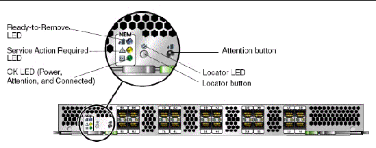
The Attention button enables you to activate (if inserting) or prepare to remove (if removing) a NEM during a hot-plug operation.
The Locator button, when pressed momentarily, flashes a white light to assist in locating the module. You can also activate the Locator LED remotely by executing a command on the CMM.
If a NEM fails or if you choose to change the I/O configuration, you will need to replace it. You can remove and replace a NEM from a powered-on system using a hot-plug operation, as well as from a powered-off system. When you remove a NEM, you must replace the module within two minutes to prevent adjacent modules from overheating.
If you are removing but not replacing the NEM, you also must install a NEM filler panel to meet FCC limits for electromagnetic interference (EMI) and to ensure proper airflow and cooling. If you encounter a problem with the NEM replacement, see the Sun Blade 8000 Series Online Help System for troubleshooting steps.
|
1. Download patch 120223-22 or 120222-22 from SunSolve:
2. Install the patch onto each of the HBAs in the NEM.
Follow the installation instructions included in the patch Readme file.
|
1. Identify which NEM to replace.
If the yellow Service Action Required LED is lit, this indicates a problem with the NEM and you might choose to replace it. Otherwise, if you want to change the I/O configuration, you can choose any NEM to replace.
2. Prepare the NEM for a hot-plug procedure using either of these methods:
a. Press the Attention button on the NEM to initiate the hot-plug removal.
b. Use the ILOM web interface or the CLI to initiate the hot-plug removal.
If the NEM fails the hot-plug preparation and its Ready-to-Remove LED does not light, see the Sun Blade 8000 Series Online Help System for troubleshooting steps.
3. When the blue Ready-to-Remove LED is lit on the NEM, physically remove the NEM.
a. Remove all cables from the NEM.
b. Press the latch on both ejector levers inward at the same time.
c. Swing out the ejector levers to their fully open position.
d. Slide the NEM out of its slot.
Support the weight of the NEM with one hand at the bottom of the NEM.
|
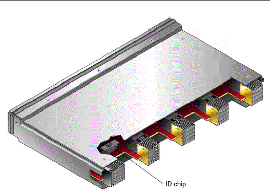
1. After you have removed the failed NEM from the chassis, locate the ID chip at the back of the board (see FIGURE 2-6).
FIGURE 2-6 Location of ID Chip
2. Grasp the edges of the ID chip and pull straight up to remove it from the board.
3. Remove the ID chip from the new NEM, and install it onto the failed board that you will be returning to Sun.
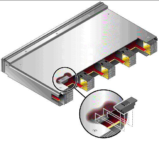
4. Install the ID chip onto the new board (see FIGURE 2-7).
a. Position the notched side of the ID chip to the left.
b. Place the ID chip directly over the connector.
c. Press down easily to seat the ID chip to the connector.
FIGURE 2-7 Installing the ID Chip
5. Install the replacement NEM into the chassis and reconnect the cables.
Copyright © 2008, Sun Microsystems, Inc. All Rights Reserved.