Sun Fire X4270 M2 Server Overview
|
This chapter provides an overview of the features of the server.
The following information is included:
1.1 Product Description
The server is an enterprise-class two-socket rackmount x64 system powered by the Intel Xeon processor, packing high-performance and expansion capability into a compact 2 rack unit footprint.
The Sun Fire X4270 M2 Server product features are listed in TABLE 1-1.
TABLE 1-1 Sun Fire X4270 M2 Server System Features
|
Feature
|
Description
|
|
Processor
|
- Intel Xeon processor 5600 series
- Supports up to two processors with two Intel processor sockets
|
|
Memory
|
18 slots for DDR3 DIMMs: Up to 144 GB of 1333-MHz ECC registered DDR3 memory
|
|
Ethernet ports
|
Four ports, 10/100/1000 Mbps, auto-negotiating through two separate controllers
|
|
Internal storage drives
|
Available in two configurations:
- Up to 12, 3.5-inch SAS, SATA, or SSD storage drives with HW RAID controller
Or
- Up to 24, 2.5-inch SAS, SATA, or SSD storage drives with HW RAID controller
|
|
Boot Drives
|
Two rear-mounted boot drives (optional).
|
|
Removable media
|
None
|
|
USB ports
|
Five USB 2.0 ports, two front, two in rear, one internal.
|
|
Service ports
|
- One RJ-45 serial management port (SER MGT)
(default connection to access service processor)
- One 10/1000-Mbps network management port (NET MGT)
(to access service processor)
- One HD-15 VGA video port
|
|
Cooling
|
- Six hot-swappable system fan modules
- An air baffle that facilitates processor/memory airflow
|
|
PCI interfaces
|
The number of PCIe2 slots supported varies with the server configuration:
- Server without rear-mounted boot drives: Three risers, each having two standard low-profile PCIe2 slots, for a total of six x8 slots. Two slots support native x8 electrical/mechanical, and four slots are active and support switched x8 electrical/mechanical.
or
- Server with rear-mounted boot drives: Two risers, each having two standard low profile PCIe2 slots, for a total of four x8 slots. Two slots support native x8 electrical/mechanical, and two slots are active and support switched x8 electrical/mechanical.
|
|
Power
|
- AC power: 100-120/200-240 V AC, 13/6.5 A, 50-60 Hz
- Up to two hot-swappable 1200W power supply units (PSUs) to provide N+N redundancy, with energy efficient design
|
|
Remote management
|
ILOM service processor providing:
- Command-line interface (CLI) over SSH
- Web-based browser interface (BUI) over HTTPS
- IPMI 2.0
- SNMP (v1, v2c, and v3)
- Remote graphical access (remote KVM) over Ethernet
- Remote storage over Ethernet
|
|
Operating system
|
Supports:
- Solaris 10 10/09 and subsequent releases
- Oracle Enterprise Linux 5.4 (64-bit)
- Red Hat Enterprise Linux 5.4 (64-bit)
- SUSE Linux Enterprise Server (SLES) 10 SP3 (64-bit)
- SLES 11 (64-bit)
- Oracle Virtual Machine (OVM) Version 2.2.1
- VMware ESX 4.0 Update 1
- VMware ESXi 4.0 Update 1
- Microsoft Windows Server 2008 SP2 (64-bit) Standard Edition/Enterprise Edition (64-bit)/Datacenter Edition(64-bit)
- Microsoft Windows Server 2008 R2 Standard Edition/Enterprise Edition/Datacenter Edition
|
|
Other software
|
Java Enterprise System with a 90-day trial license
|
See the Sun Fire X4170 M2 and X4270 M2 Servers Product Notes for additional information.
1.2 Server Chassis Overview
The following sections provide an overview of the server chassis.
1.2.1 Infrastructure Boards
The server boards are listed in TABLE 1-2.
TABLE 1-2 Infrastructure Boards
|
Board
|
Description
|
Reference
|
|
Motherboard
|
The motherboard includes 2 sockets to 2 CPU modules, slots for 18 DIMMs; 1 port for a USB flash drive, support for 2 rear-mounted, 2.5-inch SATA HDDs; and the ILOM service processor.
The ILOM service processor (SP) controls the host power and monitors host system events (power and environmental). The ILOM SP draws 3.3V standby power from the power supply when AC power is applied (without the host being powered on) even when the system is turned off.
|
Servicing the Motherboard
|
|
Power distribution board
|
This board distributes main 12V power from the power supplies to the rest of the system. It is directly connected to the connector board, and connects to the motherboard via a bus bar and ribbon cable. The power distribution board also has a connector for connecting the top-cover interlock (“kill”) switch.
|
Servicing the Power Distribution Board
|
|
Connector board
|
This board serves as the interconnect between the power distribution board and the fan power board, disk backplane, and the I/O board.
|
Servicing the Connector Board
|
|
Fan power board
|
This board carries power to the system fan modules. In addition, this board transfers sensor data for the fan modules.
|
Servicing the Fan Board
|
|
Disk backplane
|
This board includes the connectors for the storage drives, power cables, and signal cable, as well as the interconnect for the I/O board, Power and Locator buttons, and system/component status LEDs. The server can have either a 12-disk backplane or a 24-disk backplane. Each storage drive has Power/Activity and Fault LEDs.
|
Servicing the Disk Backplane
|
|
SAS expander board
|
This board serves as an interface between the disk backplane and the storage drive cables that connect to the HBA PCIe card.
|
Servicing the SAS Expander Board
|
|
PCIe2 risers
|
The number of PCIe2 risers supported varies with the server configuration:
- Server without rear-mounted boot drives: Three risers, each having two standard low-profile PCIe2 slots, for a total of six x8 slots. Two slots support native x8 electrical/mechanical, and four slots are active and support switched x8 electrical/mechanical.
OR
- Server with rear-mounted boot drives: Two risers, each having two standard low-profile PCIe2 slots, for a total of four x8 slots. Two slots support native x8 electrical/mechanical, and two slots are active and support switched x8 electrical/mechanical.
|
Servicing PCIe Risers
|
1.2.2 Dimensions and Weight
The chassis form factor dimensions and weight are listed in TABLE 1-3.
TABLE 1-3 Servers Dimensions
|
Parameter
|
Sun Fire X4270 M2 Server
|
|
Height
|
3.43 inches/87.12 mm
|
|
Width
|
16.75 inches/425.45 mm
|
|
Depth
|
30.0 inches/762.0 mm
|
|
Weight
|
65 lb/29.54 kg
|
1.2.3 Internal System Cables
The server internal cables are listed in TABLE 1-4.
TABLE 1-4 Server Cables
|
Cable
|
Connects...
|
|
Top cover interlock cable
|
To the power distribution board
|
|
Power distribution board ribbon cable
|
Between the power distribution board and the motherboard
|
|
Power supply ribbon cable
|
Between the power distribution board and the power supplies
|
|
Storage drive data cables
|
Between the motherboard HBA PCI-Express card and the SAS expander board
|
|
Fan power board cables
|
Between the connector board and fan power board
|
|
Disk backplane cables
|
Between the connector board and disk drive backplane
|
|
Front panel light pipe assembly cables
|
Between the light pipe assembly and the disk drive backplane
|
|
Rear-mounted Boot Disk Drive power and data cables
|
- Power cable: between the boot disk drive assembly to the motherboard
- Data cables: between the boot disk drive and the on-board SATA controller
|
1.3 Server Front Panel Features
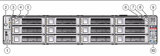
FIGURE 1-1 shows front panel features on the Sun Fire X4270 M2 Server with 12, 3.5-inch, storage drives.
FIGURE 1-1 Front Panel Features on Server With 12 Storage Drives

Figure Legend
|
1
|
Product Serial Number (PSN) label and Radio Frequency Identification (RFID) tag
|
6
|
TOP FAN Fault LED
|
|
2
|
Power Button
|
7
|
PS (Power Supply) REAR Fault LED
|
|
3
|
Locator LED/Button
|
8
|
System Overtemperature Fault LED
|
|
4
|
Service Action Required LED (System Level)
|
9
|
USB ports (2)
|
|
5
|
Power/OK LED
|
10
|
Disk Configuration Label
|
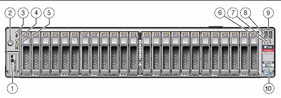
FIGURE 1-2 shows front panel features on the Sun Fire X4270 M2 Server with 24, 2.5-inch, storage drives.
FIGURE 1-2 Front Panel Features on Server With 24 Storage Drives

Figure Legend
|
1
|
Product Serial Number (PSN) Label and Radio Frequency Identification (RFID) tag
|
6
|
System Overtemperature LED
|
|
2
|
Power button
|
7
|
PS (Power Supply) REAR Fault LED
|
|
3
|
Locator LED/Locator button
|
8
|
TOP FAN Fault LED
|
|
4
|
Service Action Required LED
|
9
|
USB Ports (2)
|
|
5
|
Power/OK LED
|
10
|
Disk Drive Layout Label
|
1.4 Server Back Panel Features
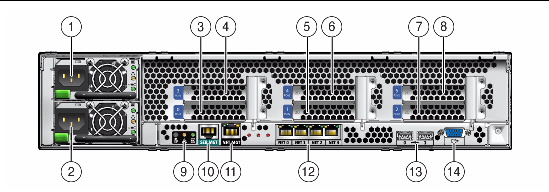
FIGURE 1-3 shows back panel features on the Sun Fire X4270 M2 Server.
FIGURE 1-3 Back Panel Features of Server Without the Rear-Mounted Boot Drives

Figure Legend
|
1
|
Power Supply Unit 1 (PSU1)
|
8
|
PCIe2 Slot 5
|
|
2
|
Power Supply Unit 0 (PSU0)
|
9
|
Rear Panel System Status LEDs:
Locator LED/Locator button (white)
Service Action Required LED (amber)
Power/OK LED (green)
|
|
3
|
PCIe2 Slot 0
|
10
|
Serial Management Port (SERMGT)
|
|
4
|
PCIe2 Slot 3
|
11
|
Network Management Port (NETMGT)
|
|
5
|
PCIe2 Slot 1
|
12
|
Gigabit Ethernet Ports (0, 1, 2, 3)
|
|
6
|
PCIe2 Slot 4
|
13
|
USB Ports 2.0 (0, 1)
|
|
7
|
PCIe2 Slot 2
|
14
|
HD-15 Video Port
|
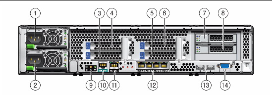
FIGURE 1-4 shows back panel features on the Sun Fire X4270 M2 Server with rear-mounted disk drives.
FIGURE 1-4 Back Panel Features of Server With Rear-Mounted Boot Drives

Figure Legend
|
1
|
Power Supply Unit (PSU) 0
|
8
|
Boot Disk Drive 0
|
|
2
|
Power Supply Unit (PSU) 1
|
9
|
Rear Panel System Status LEDs:
Locator LED/Locator button (white)
Service Action Required LED (amber)
Power/OK LED (green)
|
|
3
|
PCIe2 Slot 0
|
10
|
Serial Management Port (SERMGT)
|
|
4
|
PCIe2 Slot 3
|
11
|
Network Management Port (NETMGT)
|
|
5
|
PCIe2 Slot 1
|
12
|
Gigabit Ethernet Ports (0, 1, 2, 3)
|
|
6
|
PCIe2 Slot 4
|
13
|
USB Ports 2.0 (0, 1)
|
|
7
|
Boot Disk Drive 1
|
14
|
HD-15 Video Port
|
For a detailed description of PCIe2 slots, see PCIe Card Configuration Guidelines.
1.5 Server Status Indicators and LEDs
The server provides many status indicators and LEDs to assist you in monitoring and managing the server.
1.5.1 Server General Status Indicators
There are six system-level indicators, some of which are located on both the server front panel and the server back panel. These indicators are described in TABLE 1-5.
TABLE 1-5 Server General Status LEDs
|
Indicator/LED Name
|
Icon
|
Color
|
State Meaning
|
|
Power/OK
|

|
Green
|
This LED indicates the operational state of the chassis. This LED can be in the following states:
- OFF - AC power is not present or the ILOM boot has not completed.
- STANDY BLINK - Standby power is on, but the chassis power is off and the ILOM SP is running.
- SLOW BLINK- Startup sequence has been initiated on the host. This pattern should begin soon following powering on the server. This status indicates either 1)POST diagnostics running on server host system, or 2) the host is transitioning from the powered-on state to the standby state on shutdown.
- STEADY ON - The server is powered on and all host POST tests have completed. The server is in one of the following states: 1) the server host is booting the operating system (OS), 2) the server host is running the OS.
|
|
Service Required
|

|
Amber
|
- OFF - Normal operation
- STEADY ON - Fault present on server. This indicator lights whenever a fault LED lights for a server replaceable component.
Note - The lighting of this indicator is always accompanied by the system console message that includes a recommended service action.
|
|
Locate
|

|
White
|
- OFF - Server is operating normally
- FAST BLINK - Use ILOM to activate this indicator to enable you to locate a particular system quickly and easily.
- Pressing the Locate button will toggle LED FAST BLINK on or off.
|
|
Top Fan Failure
|
TOP FAN
|
Amber
|
Indicates that one or more of the internal system fan modules have failed.
- OFF - Indicates steady state; no service action is required.
- STEADY ON - Indicates service action required; service the fans.
|
|
Rear Power Supply Failure
|
REAR PS
|
Amber
|
Indicates that one of the server power supplies has failed.
- OFF - Indicates steady state; no service action is required.
- STEADY ON - Indicates service action required; service the power supply.
|
|
Overtemp
|

|
Amber
|
OFF - Normal operation; no service action required.
STEADY ON - The system is experiencing an overtemperature warning condition.
Note - This is a warning indication, not a fatal overtemperature. Failure to correct this might result in the system over heating and shutting down unexpectedly.
|
1.5.2 Server Fan LEDs
Each fan module has one bicolored, status LED. These LEDs are located on the server side wall adjacent to the fan modules and are visible when the top cover fan door is open. See TABLE 1-6.
TABLE 1-6 Server Fan Status LEDs
|
LED Name
|
Icon
|
Color
|
State Meaning
|
|
Fan Status
|
None
|
Bicolored: Amber/Green
|
- Amber - There is a fan fault.
- Green - Fan is properly installed and functioning correctly. No fan errors detected.
|
1.5.3 Storage and Boot Drive LEDs
There are three LEDs on each drive. See TABLE 1-7.
TABLE 1-7 Server Front Storage and Boot Disk Drive LEDs
|
LED Name
|
Icon
|
Color
|
State Meaning
|
|
Activity
|

|
Green
|
- OFF - Power is off or installed drive is not recognized by the system.
- STEADY ON - The drive is engaged and is receiving power.
- STANDBY BLINK - There is disk activity. LED blinks on and off to indicate activity.
|
|
Service Required
|

|
Amber
|
- OFF - Normal operation.
- STEADY ON - The system has detected a fault with the storage drive.
|
|
Ready to Remove
|

|
Blue
|
The storage drive can be removed safely during a hot-plug operation.
|
1.5.4 Power Supply LEDs
There are three LEDs on each power supply. These LEDs are visible from the rear of the server. See TABLE 1-8.
TABLE 1-8 Server Power Supply LEDs
|
LED Name
|
Icon
|
Color
|
State Meaning
|
|
DC OK
|

|
Green
|
- STEADY ON - Normal operation. DC output voltage is within specification.
- OFF: 12V power is disabled.
|
|
Service Required
|

|
Amber
|
- OFF - Normal operation; no service action required.
- STEADY ON - The power supply (PS) has detected a PS fan failure, PS overtemperature, PS over current, or PS over/under voltage.
|
|
AC OK
|
~AC
|
Green
|
- OFF - No AC power is present.
- STEADY ON - Normal operation. Input power is above minimum specification.
|
1.5.5 Motherboard LEDs
The motherboard and modules that are installed on the motherboard contain several LEDs, which are described in the following sections:
| Note - A super capacitor provides sufficient power for the motherboard LEDs to be lit for up to 15 minutes after the removal of the server’s top cover. After 15 minutes, the capacitor might be discharged enough so that lighting the fault LEDs is not possible.
|
1.5.5.1 DDR3 DIMM Fault LEDs
Each of the 18 DDR3 DIMM slots on the motherboard has an amber fault LED associated with it. If ILOM determines that a DIMM is faulty, pressing the Fault Remind button on the motherboard signals the service processor to light the fault LED(s) associated with the faulted DIMM(s).
1.5.5.2 CPU Fault LEDs
The motherboard includes a fault LED adjacent to each of the two CPU sockets. These LEDs indicate when a CPU is faulty. For example, if on reboot the BIOS detects that there are uncorrectable CPU errors recorded in the MCA registers apparently left over from the previous boot, then the BIOS and ILOM work together to record and diagnose these errors. If it is determined that a CPU is faulty, pressing the Fault Remind button on the motherboard signals the service processor to light the fault LED(s) associated with the faulted CPU(s).
1.5.5.3 Fault Remind Super Capacitor Power LED
This LED is located next to the Fault Remind button and is powered from the super capacitor that powers the fault LEDs on the motherboard. This LED lights to indicate to the user that the fault remind circuitry is working properly in cases where no components have failed and, as a result, none of the component fault LEDs illuminate.
1.5.5.4 Connector Board 12V Power LEDs
The connector board has two LEDs (CR7 and CR8) that light green when +12 volts is being applied to the connector board. These LEDs are located to the left of the fan board connector on the connector board. For the location of the fan board connector, see TABLE 5-1 and FIGURE 5-9.
1.5.5.5 Power distribution Board 5V Power LED
The power distribution board (PDB) 5V power LED (CR0601) lights green when +5 volts is being applied to the PDB. This LED is located to the right of the motherboard ribbon cable connector when viewing the PDB from the front of the server.
1.5.5.6 3.3V_STANDBY OK LED
The service instructions for all internal components require that all AC power be removed from the power supplies prior to the server’s top cover being removed. This green LED is located on the motherboard near the rear of the server and it lights to inform a service technician that the motherboard is receiving standby power from at least one of the power supplies. This indicator is provided to help prevent service actions on the server’s internal components while the AC line-cords are installed and power is being supplied to the server.
| Sun Fire X4270 M2 Server Service Manual
|
821-0488-12
|
   
|
Copyright © 2010, Oracle and/or its affiliates. All rights reserved.


