| C H A P T E R 2 |
|
Preparing to Service the System |
This chapter describes how to prepare the server for servicing.
The following topics are covered:
This section describes important safety information that you need to know prior to removing or installing parts in the Sun Fire X4270 M2 Server.

|
Caution - Hazardous voltage present.Never attempt to run the server with the cover removed. |

|
Caution - Equipment damage possible.The covers must be in place for proper airflow. |
For your protection, observe the following safety precautions when setting up your equipment:
The Sun Fire X4270 M2 Server can be serviced with the following tools:
To obtain support for your server, you need your chassis serial number. The chassis serial number is located on a sticker on the front of the server and on another sticker on the top of the server.
Refer to the following topics in this section to power on and off a server:
1. Verify that the server is in the standby power state.
In the standby power state, the OK/Power LED on the front panel of the server blinks (0.1 second on, 2.9 seconds off). The standby power state indicates that the server SP is active but the server host is powered off.
For the location of the OK/Power LED, see FIGURE 1-1.
2. Apply full power to the server SP and host.
For the location of the Power button on the server, see FIGURE 1-1.
The Power/OK LED illuminates a SLOW BLINK while the system is executing its BIOS firmware. The Power/OK LED illuminates STEADY ON when the BIOS firmware completes and the operating system boot begins.
To remove main power from the server, use one of the methods shown in the following table.
|
Press and release the Power button on the front panel (FIGURE 1-1). Pressing the power button causes Advanced Configuration and Power Interface (ACPI)-enabled operating systems to perform an orderly shutdown of the operating system. Servers not running ACPI-enabled operating systems will shut down to standby power mode immediately. Note - Some operating systems might prompt the user for confirmation of the shutdown before actually turning off the system. |
|
|
Press and hold the Power button for at least five seconds until the main power is off and the server enters standby power mode (FIGURE 1-1). |
|
|
|
|
|
See Power Off the Server Using the ILOM SP Command-Line Interface. |

|
Caution - To completely power off the server, you must disconnect the AC power cords from the back panel of the server. |
You can use the ILOM service processor (SP) to perform a graceful shutdown of the server and ensure that all of your data is saved and the server is ready for restart.
ssh root@host (Where host is either a hostname, when using DNS, or an ipaddress.)
Password: root_password (The default password is changeme.)
The ILOM command-line interface (CLI) prompt appears (->).
Depending on the type of problem, you might want to view server status or log files, or run diagnostics before you shut down the server.
2. Notify affected users that the server will be shut down.
3. Save any open files and quit all running programs.
Refer to your application documentation for specific information.
4. Power down the server. Type:
-> stop /SYS (for a Graceful shutdown as defined in TABLE 2-1)
-> stop -f/SYS (for an Emergency Shut as defined in TABLE 2-1)
For additional information, refer to the Oracle Integrated Lights Out Manager (ILOM) 3.0 Documentation Collection (formerly called the Sun Integrated Lights Out Manager).
The Basic Input/Output System (BIOS) has a Setup Utility stored in the BIOS flash memory. The Setup Utility reports system information and can be used to configure the BIOS settings. The configurable data is provided with context-sensitive help and is stored in the system's battery-backed CMOS RAM. If the configuration stored in the CMOS RAM is invalid, the BIOS settings return to their default optimal values.
There are seven menus in the BIOS Setup Utility, which appear in this order: Main, Advanced, PCI, Boot, Security, Chipset, and Exit. To navigate the menus or options listed on the menu, use the arrow keys. The options or fields that you can configure on a menu appear in color. For further instructions on how to navigate and change settings in the BIOS Setup Utility, refer to the online instructions provided on the menu.
For additional information about the BIOS operations and menu options available on your server, refer to the following sections:
Refer to the following sections for information when booting the BIOS and other
set up considerations:
At system startup, the BIOS performs a power-on self-test that checks the hardware on your server to ensure that all components are present and functioning properly. TABLE 2-2 identifies the events that can occur during BIOS POST, as well as specifies whether these events can prevent the host from powering-on.
|
Memory Correctable ECC (error correction code) error detected |
||
|
All installed memory has experienced an unrecoverable failure |
||
Each power-on-self-test (POST) diagnostic is a low-level test designed to pinpoint faults in a specific hardware component. If the POST diagnostic discloses an F1 or F2 error, it typically reports the following information about the error:
TABLE 2-3 lists some of the F1 and F2 error messages that could appear during the POST diagnostics along with instructions for how to possibly resolve the error reported.
The BIOS POST memory testing is performed as follows:
1. The first megabyte of DRAM is tested by the BIOS before the BIOS code is copied from ROM to DRAM.
2. After exiting out of DRAM, the BIOS performs a simple memory test (where a write/read of every location with the pattern 55aa55aa is performed).
| Note - The simple memory test is performed only if Quick Boot is not enabled from the Boot Settings Configuration screen. Enabling Quick Boot causes the BIOS to skip the memory test. |
3. The BIOS polls the memory controllers for both correctable and non-correctable memory errors and logs those errors into the SP.
4. The message, BMC Responding appears at the end of POST.
The server supports four 10/100/1000BASE-T Gigabit Ethernet ports on the rear of the chassis. For port locations, see FIGURE 1-2.
The device naming for the Ethernet interfaces is reported differently by different interfaces and operating systems. See TABLE 2-4 for the physical (BIOS) and logical (operating system) naming conventions used for each interface.
|
eth0[1] |
||||
|
eth0[2] |
||||
|
eth0[3] |
||||
|
vmnic#[4] |
The order in which the BIOS detects the Ethernet ports during boot time, and the corresponding drivers that control those ports, are listed below:
TABLE 2-5 provides descriptions for the seven top-level BIOS setup menus.
See BIOS Setup Utility Menu Screens for examples of each of these screens.
FIGURE 2-1 identifies the sub-menus that you can access from each of the seven top-level BIOS menus.
FIGURE 2-1 BIOS Configuration Utility Menu Tree
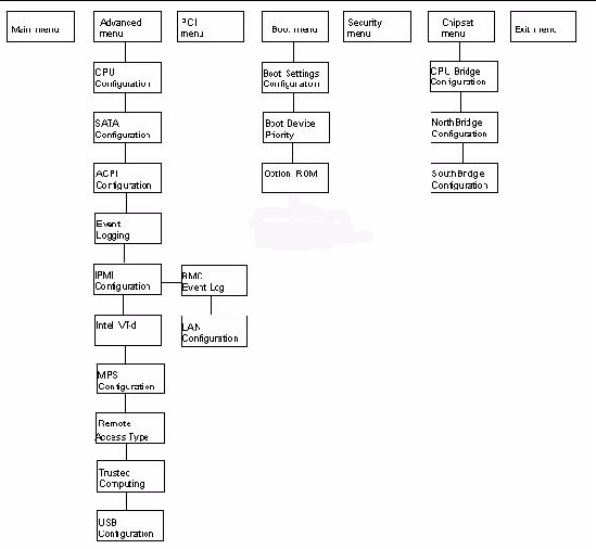
For an example of the options that are available on the BIOS Setup Utility menus, see Appendix B.
TABLE 2-6 provides a description of the BIOS Setup Utility hot keys and the corresponding serial connection key combinations.
|
Access the BIOS Setup Utility if there is an error during the boot process |
||
|
Enter BIOS Setup Utility while the system is performing the power-on self test (POST) |
||
|
Select the BBS Popup menu, which allows you to select a boot device |
||
|
F10[5] |
||
You can access BIOS Setup Utility screens from the following interfaces:
The following procedure describes the steps for accessing the BIOS Setup Utility menus.
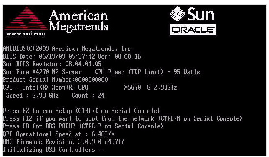
1. Power-on or power-cycle the server.
The Boot Option screen appears (FIGURE 2-2).
2. To enter the BIOS Setup Utility, do the following:
a. Wait for the last line of the screen output to change to Initializing USB Controllers..Done
This will take several seconds.
b. When Done appears, immediately press the F2 key.
| Note - If there is an error during the boot process, you can press F1 to access the BIOS Setup Utility. |
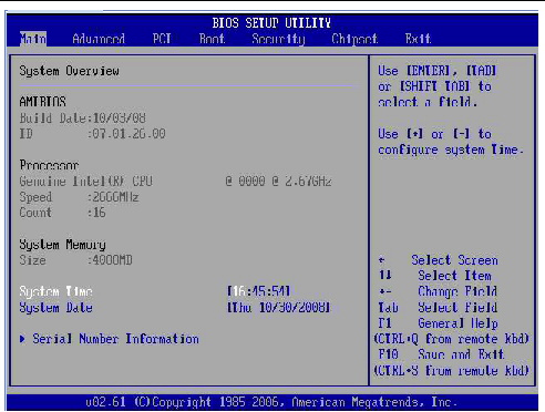
The BIOS Setup Utility dialog appears (FIGURE 2-3).
FIGURE 2-3 BIOS Setup Utility: Main - System Overview
3. Use the left and right arrow keys to select the different menu options.
4. As you select each menu option, the top-level screen for that menu option appears.
5. To select an option on a top-level screen, use the up and down arrow keys to scroll up and down the options presented.
Only options that can be modified are highlighted when you press the up and down arrow keys.
6. Modify the setup field and press the Esc key to save the changes and exit the screen.
Some screens present a confirmation dialog box that enables unwanted changes to be retracted.
7. On sub-screens that only provide configuration information and cannot be modified, press the Esc key to exit the screen.
8. To continue modifying other setup parameters, repeat Step 3 through Step 7. Otherwise, go to Step 9.
9. Press and release the right arrow key until the Exit menu screen appears.
10. Follow the instructions on the Exit menu screen to save or discard your changes and exit the BIOS Setup Utility.
If you intend to use the Trusted Platform Module (TPM) feature set that is provided in Windows 2008, you must configure the server to support this feature.
TPM enables you to administer the TPM security hardware in your server. For additional information about implementing this feature, refer to the Windows Trusted Platform Module Management documentation provided by Microsoft.
1. Access the BIOS Setup Utility menus.
For instructions, see Access BIOS Setup Utility Menus.
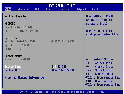
When BIOS is started, the Main BIOS Setup Utility top-level, System Overview screen appears (FIGURE 2-4).
FIGURE 2-4 Main - System Overview screen
2. In the BIOS Setup Utility screen, select the Advanced menu option.
The Advanced Settings screen appears (FIGURE 2-5).
FIGURE 2-5 Advanced Settings Screen
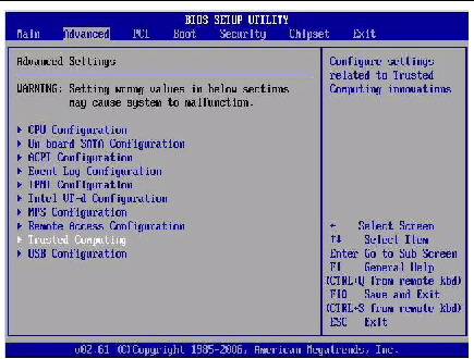
3. In the Advanced Settings screen, select Trusted Computing and press Enter.
The Trusted Computing screen appears (FIGURE 2-6).
FIGURE 2-6 Trusted Computing Screen
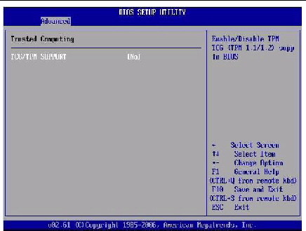
4. In the Trusted Computing screen, select the TCG/TPM Support.
5. In the pop-up dialog box, set the TCG/TPM Support option to Yes and click Ok.
The updated Trusted Computing screen appears and shows that the TCG/TPM Support setting has changed to Yes (FIGURE 2-7).
FIGURE 2-7 Trusted Computing Screen Showing TCG/TPM Support Enabled
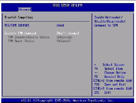
| Note - In the above screen, the Execute TPM Command setting shows the default, Don’t Change. |
6. In the Trusted Computing screen, select the Execute TPM Command option setting.
7. In the pop-up tab, set the Execute TPM Command option to Enabled and click Ok.
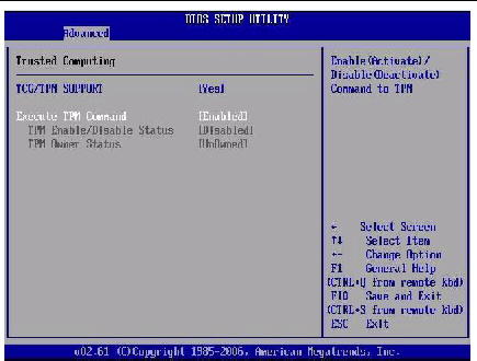
The updated Trusted Computing screen appears and shows that the Execute TPM Command setting has changed to Enabled (FIGURE 2-8).
FIGURE 2-8 Execute TPM Command - Setting Enabled
8. Press F10 to save the changes and exit the BIOS Setup Utility.
9. To verify that TPM support is configured, do the following:
b. To enter the BIOS Setup Utility, press the F2 key while the system is performing the power-on self-test (POST).
When BIOS is started, the Main BIOS Setup Utility top-level screen appears (FIGURE 2-4).
c. Select Advanced --> Trusted Computing and press Enter.
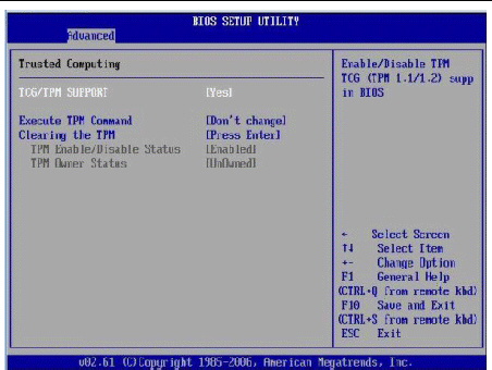
The updated Trusted Computing screen appears (FIGURE 2-9).
Confirm that the TCG/TPM Support setting is set to Yes and the TPM Enabled/Disable Status is set to Enabled.
FIGURE 2-9 Updated TPM Enabled/Disabled Status Setting
This completes the TPM configuration.
You can assign an IP address for the server SP from the BIOS Setup Utility on the IPMI LAN configuration menu. Alternatively, you can also specify the LAN settings for the SP using ILOM. For instructions for setting the IP address in ILOM, see the Oracle Integrated Lights Out Manager (ILOM) 3.0 Documentation Collection.
For instructions on configuring SP LAN settings using the BIOS Setup Utility, see the following sections:
1. Access the BIOS Setup Utility menus.
For instructions, see Access BIOS Setup Utility Menus.
2. In the BIOS Setup Utility menus, use the arrow keys (or Tab key) to navigate to the Advanced menu.
3. In the Advanced menu, select IPMI Configuration.
4. In the IPMI Configuration menu, select LAN Confutation.
The LAN Configuration screen appears (FIGURE 2-10).
FIGURE 2-10 BIOS Setup Utility: Advanced - LAN Configuration
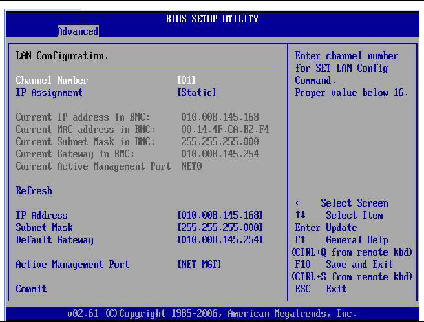
5. In the LAN Configuration screen, use the arrow keys to select and specify the appropriate LAN configuration settings.
6. Press F10 to save the changes and exit the BIOS.
1. Power on the server (or restart the server if it is running).
2. When the BIOS splash screen or text prompt appears during the power-on self-test (POST) operation, press F2 to access the BIOS Setup Utility.
3. Using the left and right arrow keys on the keyboard, navigate to the Advanced tab.
The Advanced Settings screen appears (FIGURE 2-5).
4. Using the up and down arrow keys, select the IPMI Configuration option and press Enter to go to the subscreen.
The IPMI Configuration subscreen appears.
5. Using the up and down arrow keys, select the Set LAN Configuration option and press Enter.
The LAN Configuration subscreen appears and shows the current ILOM SP IP address.
a. Select Set LAN Configuration, then use the arrow keys to select settings.
b. Specify the appropriate settings, then proceed to Step 7.
7. Select Commit and press Enter.
8. Allow about five seconds for the Commit to complete, then select Refresh and press Enter.
9. Select Refresh a second time and press Enter to confirm that the IP address information has been set.
10. Press F10 to save any changes you made and to exit the BIOS Setup Utility.
The BIOS Option ROM is 128 Kbytes. Of these 128 Kbytes, approximately 80 Kbytes are used by the VGA controller, the disk controller, and the network interface card. Approximately 48 Kbytes remain to be shared by the Option ROMs on all bootable PCI-Express plug-in cards.
1. Access the BIOS Setup Utility menus.
For instructions, see Access BIOS Setup Utility Menus.
2. In the BIOS Setup Utility menus, use the arrow keys (or Tab key) to navigate to the Boot menu.
The Boot menu appears (FIGURE 2-11).
FIGURE 2-11 BIOS Setup Utility: Boot - Option ROM Configuration
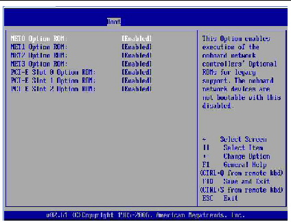
3. In the Boot menu listing the Option ROM settings, highlight the applicable Option ROM setting to modify, then press Enter.
A dialog box appears listing the available settings.
4. In the dialog box, do one of the following:
5. Press F10 to save the changes and exit the BIOS.
The BIOS is updated whenever you update the ILOM SP firmware. For instructions about updating the firmware, refer to the Oracle Integrated Lights Out Manager (ILOM) 3.0 Documentation Collection.
The following components can be serviced with the server in the maintenance position:
If the server is installed in a rack with extendable slide rails, use this procedure to extend the server to the maintenance position.
1. Verify that no cables will be damaged or will interfere when the server is extended.
Although the cable management arm (CMA) that is supplied with the server is hinged to accommodate extending the server, you should ensure that all cables and cords are capable of extending.
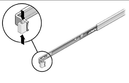
2. From the front of the server, release the two slide release latches (FIGURE 2-12).
Squeeze the green slide release latches to release the slide rails.
FIGURE 2-12 Slide Release Latches
3. While squeezing the slide release latches, slowly pull the server forward until the slide rails latch.
The server is now in the extended maintenance position.
The server must be removed from the rack to service the following components:

|
Caution - The server weighs 36 lb (16.36 kg). If necessary, use two people to dismount and carry the chassis. |
1. Disconnect all the cables and power cords from the server.
2. Extend the server to the maintenance position.
See Extend the Server to the Maintenance Position.
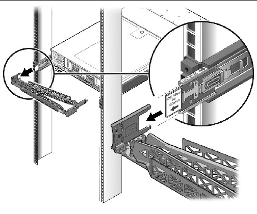
3. Press the metal lever that is located on the inner side of the rail to disconnect the cable management arm (CMA) from the rail assembly (FIGURE 2-13).
The CMA is still attached to the cabinet, but the server chassis is now disconnected from the CMA.
FIGURE 2-13 Metal Lever and Cable Management Arm
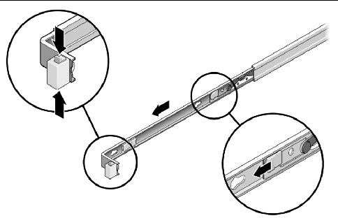
4. From the front of the server, pull the release tabs forward and pull the server forward until it is free of the rack rails (FIGURE 2-14).
A release tab is located on each rail.
FIGURE 2-14 Release Tabs and Slide Assembly
5. Set the server on a sturdy work surface.
Each server is shipped with module-replacement filler panels for CPUs, storage drives, DDR3 memory modules (DDR3 DIMMs), PCIe cards, and power supplies. These filler panels are installed at the factory and must remain in the server until you replace them with a purchased option.
As needed, consult the following sections when removing and replacing a server component:
A filler panel is an empty metal or plastic enclosure that does not contain any functioning system hardware or cable connectors. These panels must remain in any unused module slots (CPU, storage drives, DDR3 DIMMs, PCIe cards, power supplies) to ensure proper airflow throughout the system. If you remove a filler panel and continue to operate your system with an empty module slot, the operating performance of your system could decline.
Before you can install a optional server component into the server, you must remove the filler panel from the location into which you intend to install the component. When you remove a CPU, storage drive, DDR3 DIMM, PCIe card, or a power supply from the server, you must install either a replacement for component removed or a filler panel.
TABLE 2-7 describes how to remove and install server filler panels.
Electrostatic discharge (ESD) sensitive devices, such as the motherboards, PCIe cards, storage drives, and memory cards, require special handling.

|
Caution - You must disconnect both power supplies before servicing any of the components documented in this chapter. |
Wear an antistatic wrist strap and use an antistatic mat when handling components such as storage drive assemblies, circuit boards, or PCIe cards. When servicing or removing server components, attach an antistatic strap to your wrist and then to a metal area on the chassis. Following this practice equalizes the electrical potentials between you and the server.
| Note - An antistatic wrist strap is not included in the Accessory Kit for the Sun Fire X4270 M2 Server. However, antistatic wrist straps are still included with options and components. |
Place ESD-sensitive components on an antistatic mat.
1. Prepare an antistatic surface to set parts on during the removal, installation, or replacement process.
Place ESD-sensitive components such as the printed circuit boards on an antistatic mat. The following items can be used as an antistatic mat:
2. Attach an antistatic wrist strap.
When servicing or removing server components, attach an antistatic strap to your wrist and then to a metal area on the chassis.
The top cover and fan door are integrated.
| Note - Servicing some components requires that the top cover be removed. |
1. Disconnect the AC power cords are disconnected from the server power supplies.
2. Unlatch the fan module door (FIGURE 2-15 [1]).
Press the two green release buttons on the sides of the fan module door to release the door. Rotate the fan module door to the open position and hold it there.
FIGURE 2-15 Removing the Top Cover
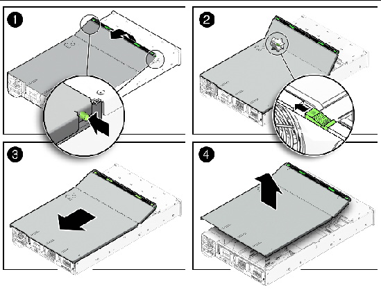
Locate the green tab to the right (facing the front of the server) and to the rear of the fan modules and slide the tab to the right-most position [2].
4. Slide the top cover toward the rear of the server about a 0.5 inch (12 mm) [3].
5. Lift up and remove the top cover [4].
Before you can remove the server’s disk backplane, you must first remove the server’s front cover.
| Note - This procedure only applies to the server with 2.5-inch storage drives. |
| Note - Servicing some components requires that the server’s front cover be removed. |
1. Disconnect the AC power cords are disconnected from the server power supplies.
2. Remove the server’s top cover.
See Removing the Server’s Top Cover.
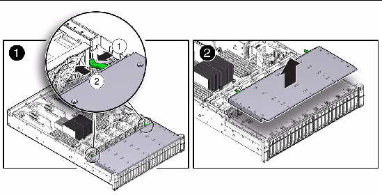
3. Remove the server’s front cover (FIGURE 2-16).
a. Press the two levers on the back of the cover inward toward each other and hold [1]
b. Slide the front cover toward the rear of the server about a 0.25 inch (6 mm) [1].
c. Grasp the rear of the cover and lift it up and off the server [2].
FIGURE 2-16 Removing the Server’s Front Cover
Copyright © 2010, Oracle and/or its affiliates. All rights reserved.