| Sun Fire X4270 M2 Server Service Manual |
| Sun Fire X4270 M2 Server Service Manual |
| C H A P T E R 4 |
 Servicing Motherboard Components
 |
This chapter describes how to replace the motherboard and its components in the Sun Fire X4270 M2 Server.
| Note - Before performing any of the procedures in this chapter, perform the procedures described in Chapter 2, Preparing to Service the System. |
The following topics are covered in this chapter:

|
Caution - Hazardous voltage present.Never attempt to run the server with the cover removed. |

|
Caution - Equipment damage possible.The cover must be in place for proper airflow. |
The motherboard components that are replaceable are shown in FIGURE 4-1.
FIGURE 4-1 Location of Motherboard Components

|
|
Caution - These procedures require that you handle components that are sensitive to static discharge. This sensitivity can cause the component to fail. To avoid damage, ensure that you follow antistatic practices as described in Performing Electrostatic Discharge and Antistatic Prevention Measures. |
The Sun Fire X4270 M2 Server supports a variety of DIMM configurations that can include quad-rank (QR) DIMMs, dual-rank (DR) DIMMs, or single-rank (SR) DIMMs. When replacing or upgrading a DIMM on the server you should consider the following:
For details, see DIMM and CPU Physical Layout.
For details, see DIMM Population Rules.
For details, see DIMM Rank Classification Labels.
For details, see Locations of Faulty DIMMs Using ILOM Versus BIOS.
For details, see Inconsistencies Between DIMM Fault LEDs and the BIOS Mapping of Faulty DIMMs.
For details, see Remove Faulty DIMMs.
For details, see Install DDR3 DIMMs.
For details, see Error Correction and Parity.
The physical layout of the DIMMs and CPUs is shown in FIGURE 4-2 and TABLE 4-1.
FIGURE 4-2 CPU and DIMM Physical Layout

The DIMM population rules for the servers are as follows:
1. Do not populate any DIMM sockets next to an empty CPU socket. Each processor contains a separate memory controller.
2. Each CPU can support a maximum of:
3. Each CPU can support single DIMMs or two DIMMs per channel.
4. Each CPU can support a single DIMM in channel 0, or one DIMM each in channels 0 and 1.
5. A server CPU will support both 1.35v and 1.5v DIMMs, but will default to the higher voltage.
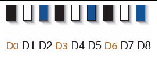
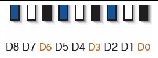
6. Populate DIMMs by location according to the following rules:
For example, populate D8/D5/D2 first; then D7/D4/D1 second; and finally, D6/D3/D0. See FIGURE 4-2.
Note that QR DIMMs are supported only in white sockets if adjacent blue socket contains a QR DIMM.
7. For maximum performance, apply the following rules:
|
DIMM speed rules are as follows:
|
|
|
The system operates all memory only as fast as the slowest DIMM configuration. |
DIMMs come in a variety of ranks: single, dual, or quad. Each DIMM is shipped with a label identifying its rank classification. TABLE 4-3 identifies the corresponding rank classification label shipped with each DIMM.
ILOM and BIOS use different formats to identify the location of a faulty DIMM.
TABLE 4-4 shows the mapping of faulty DIMM locations as reported by ILOM and BIOS.
When a single DIMM is marked as faulty by ILOM (for example, fault.memory.intel.dimm.training-failed is listed in the SP Event Log), BIOS might map out the entire memory channel that contains the faulty DIMM as failing, that is, up to three DIMMs. As a result, the memory available to the operating system is reduced.
However, when the Fault Remind button is pressed, only the fault LED associated with the faulty DIMM lights. The fault LEDs for the other two DIMMs in the memory channel remain off. Therefore, you can correctly identify the faulty DIMM.
When the faulty DIMM is replaced and the DIMM fault is cleared using ILOM, the memory available to the operating system returns to normal. For instructions for clearing DIMM faults, see the Oracle Integrated Lights Out Manager (ILOM) 3.0 Supplement for Sun Fire X4170 M2 and X4270 M2 Servers (821-0489).
| Note - The DDR3 memory DIMMs are customer-replaceable units (CRUs) and do not require an authorized service provider for replacement. |
1. Prepare the server for service.
a. Power off the server and disconnect the power cord (or cords) from the server power supply (or supplies).
See Power Off the Server.
b. Extend the server into the maintenance position.
See Extending the Server to the Maintenance Position.
c. Attach an antistatic wrist strap.
See Performing Electrostatic Discharge and Antistatic Prevention Measures.
See Removing the Server’s Top Cover.
2. Remove the faulty DDR3 DIMM(s).
a. To identify the location of the faulty DDR3 DIMMS, press the Fault Remind button on the motherboard (FIGURE 4-3).
FIGURE 4-3 Fault Remind Button

b. Note the location of faulty DDR3 DIMMs.
Faulty memory DIMMs are identified with a corresponding amber LED on the motherboard (FIGURE 4-4).
FIGURE 4-4 Memory DIMM Fault LED Locations

c. To remove the faulty DIMM do the following:
i. Rotate both DIMM slot ejectors outward as far as they will go.
The DIMM is partially ejected from the socket (FIGURE 4-5).
ii. Carefully lift the DIMM straight up to remove it from the socket.
d. Replace each faulty DIMM with either another DIMM of the same rank size (quad rank, dual rank, or single rank) or a DIMM filler panel.
For DIMM replacement instructions, see Install DDR3 DIMMs.
|
|
Caution - If you are not immediately inserting a replacement DIMM into the empty DIMM socket, insert a DIMM filler panel in the socket to ensure adequate cooling and reduce the possibility of a system shutdown. For instructions for installing a DDR3 filler panel, see Filler Panel Removal and Installation. |
FIGURE 4-5 DIMM Socket Release and Alignment

1. Unpack the replacement DDR3 DIMMs and place them on an antistatic mat.
2. Ensure that the replacement DIMMs match the sizes as the DIMMs they are replacing.
You must not replace a dual-rank DIMM with a quad-rank DIMM and vice versa. If you violate this rule, the performance of the server might be adversely affected. For DIMM population rules, see DIMM Population Rules.
a. Ensure that the ejector tabs are in the open position.
b. Line up the replacement DIMM with the connector (FIGURE 4-6).
Align the notch in the DIMM with the key in the connector. The notch ensures that the DIMM is oriented correctly.

c. Push the DIMM into the connector until the ejector tabs lock the DIMM in place.
If the DIMM does not easily seat into the connector, verify that the notch in the DIMM is aligned with the key in the connector as shown in FIGURE 4-6. If the notch is not aligned, damage to the DIMM might occur.
4. Repeat Step 3 until all replacement DIMMs are installed.
5. Return the server to operation.
See Installing the Server Top Cover.
b. Return the server to the normal rack position.
See Returning the Server to the Normal Rack Position.
c. Reconnect the power cord (or cords) to the server power supply (or supplies) and power on the server.
Verify that the AC Present LED is lit.
6. Use ILOM to clear DDR3 DIMM faults.
For instructions for clearing DIMM faults, see the Oracle Integrated Lights Out Manager (ILOM) 3.0 Supplement for Sun Fire X4170 M2 and X4270 M2 Servers (821-0489).
The server’s processor provides parity protection on its internal cache memories and error-correcting code (ECC) protection of the data. The system can detect and log to the ILOM event log the following types of errors:
Advanced ECC corrects up to 4 bits in error on nibble boundaries, as long as they are all in the same DRAM. If a DRAM fails, the DIMM continues to function.
For instructions for clearing DIMM faults, see the Oracle Integrated Lights Out Manager (ILOM) 3.0 Supplement for Sun Fire X4170 M2 and X4270 M2 Servers (821-0489).
You must remove the air baffle when removing and installing the motherboard on Sun Fire X4270 M2 Server.
|
|
Caution - To prevent the system from overheating, ensure that the air baffle is correctly installed before powering on the server. |
1. Prepare the server for service.
a. Power off the server and disconnect the power cord (or cords) from the server power supply (or supplies).
See Power Off the Server.
b. Extend the server to the maintenance position.
See Extending the Server to the Maintenance Position.
c. Attach an antistatic wrist strap.
See Performing Electrostatic Discharge and Antistatic Prevention Measures.
See Removing the Server’s Top Cover.
2. Open the air baffle as shown in FIGURE 4-7.
Grasp the air baffle at the bottom and lift it up and out of the way.
FIGURE 4-7 Opening the Air Baffle

1. Prepare the server for service.
a. Power off the server and disconnect the power cord (or cords) from the server power supply (or supplies).
See Power Off the Server.
b. Extend the server to the maintenance position.
See Extending the Server to the Maintenance Position.
c. Attach an antistatic wrist strap.
See Performing Electrostatic Discharge and Antistatic Prevention Measures.
See Removing the Server’s Top Cover.
2. Remove the air baffle (FIGURE 4-8).
a. Press the air baffle connectors [1] outward.
b. Lift the air baffle up and out of the server [2].
FIGURE 4-8 Removing the Air Baffle

|
|
Caution - When the server is in operation, ensure that the air baffle is correctly installed to prevent the system from overheating. |
1. Install the air baffle into the chassis.
a. Press the air baffle connectors outward.
b. Insert the air baffle in to the server, and lower it to its down position.
2. Return the server to operation.
See Installing the Server Top Cover.
b. Return the server to the normal rack position.
See Returning the Server to the Normal Rack Position.
c. Reconnect the power cord (or cords) to the server power supply (or supplies) and power on the server.
Verify that the AC Present LED is lit.
PCIe cards are installed on vertical risers. You must remove the relevant riser to remove and replace a PCIe card. You must remove all three PCIe risers when replacing the motherboard.
|
|
Caution - These procedures require that you handle components that are sensitive to static discharge. This sensitivity can cause the component to fail. To avoid damage, ensure that you follow antistatic practices as described in Performing Electrostatic Discharge and Antistatic Prevention Measures. |
|
|
Caution - Ensure that all power is removed from the server before removing or installing risers. You must disconnect the power cables before performing this procedure. |
The following topics are covered in this section:
1. Prepare the server for service.
a. Power off the server and disconnect the power cord (or cords) from the power supply (or supplies).
See Power Off the Server.
b. Extend the server to the maintenance position.
See Extending the Server to the Maintenance Position.
c. Attach an antistatic wrist strap.
See Performing Electrostatic Discharge and Antistatic Prevention Measures.
See Removing the Server’s Top Cover.
2. If you are servicing a PCIe card, locate its position in the system.
3. Disconnect any data cables connected to the cards on the PCIe riser being removed.
Label the cables to ensure proper connection later.
4. Remove the back panel PCI crossbar (FIGURE 4-9).
a. Loosen the two captive Phillips screws on the end of the PCI crossbar [1].
b. Lift the PCI crossbar up and back to remove it from the chassis [1].
5. Remove the PCIe riser from the system (FIGURE 4-9).
a. Loosen the captive screw holding the riser to the motherboard [2].
b. Lift up the riser and any PCIe cards that are attached to it as a unit [2].
The server can have up to three PCIe risers. Each riser can support two PCIe cards.
FIGURE 4-9 Removing a PCIe Riser
.")
1. Lower the PCIe riser and any cards attached to it into the system (FIGURE 4-10 [1]).
Slide the back of the riser into the motherboard back panel stiffener.
2. Tighten the screw that secures the riser to the motherboard [1].
3. Install the back panel PCI crossbar [2].
Slide the crossbar down over the PCIe risers. Secure the PCI crossbar to the chassis with two captive Phillips screws.
FIGURE 4-10 Installing a PCIe Riser
.")
4. Return the server to operation.
a. Install the server top cover.
See Installing the Server Top Cover.
b. Return the server to the normal rack position.
See Returning the Server to the Normal Rack Position.
c. Connect any data cables you removed to service the PCIe cards.
d. Reconnect the power cord (or cords) to the power supply (or supplies).
Verify that the AC Present LED is lit.
5. Use ILOM to clear the server PCIe riser fault.
For instructions for clearing an PCIe riser faults, see the Oracle Integrated Lights Out Manager (ILOM) 3.0 Supplement for Sun Fire X4170 M2 and X4270 M2 Servers (821-0489).
See PCIe Card Configuration Guidelines for PCIe card configuration guidelines.
|
|
Caution - These procedures require that you handle components that are sensitive to static discharge. This sensitivity can cause the component to fail. To avoid damage, ensure that you follow antistatic practices as described in Performing Electrostatic Discharge and Antistatic Prevention Measures. |
|
|
Caution - Ensure that all power is removed from the server before removing or installing expansion cards. You must disconnect the power cables before performing these procedures. |
The following topics are covered in this section:
See TABLE 4-5 for a list of PCIe option cards supported and the applicable installation guide.
|
Sun Storage 6 Gb SAS RAID PCIe HBA, Internal (SGX-SAS6-R-INT-Z)[2] |
This card connects to internal storage devices, that is, devices that are physically located inside the system chassis and supports RAID. |
The “Hardware Installation and Removal” chapter in the Sun Storage 6 Gb SAS PCIe RAID HBA, Internal Installation Guide For HBA Models SGX-SAS6-R-INT-Z and SG-SAS6-R-INT-Z (820-7885) |
|
Sun Storage 6 Gb SAS RAID PCIe HBA, External (SGX-SAS6-R-EXT-Z) |
The “Hardware Installation and Removal” chapter in the Sun Storage 6 Gb SAS PCIe RAID HBA, External Installation Guide For HBA Models SGX-SAS6-R-EXT-Z and SG-SAS6-R-EXT-Z (820-7886) |
|
|
Connects to internal storage devices, that is, devices that are physically located inside the system chassis. |
The “Hardware Installation and Removal” chapter in the Sun Storage 6 Gb SAS PCIe HBA, Internal Installation Guide For HBA Models SGX-SAS6-INT-Z and SG-SAS6-INT-Z (820-7889) |
|
|
The “Hardware Installation and Removal” chapter in the Sun Storage 6 Gb SAS PCIe HBA, External Installation Guide For HBA Models SGX-SAS6-EXT-Z and SG-SAS6-EXT-Z (820-7890) |
| Note - Some of the SAS PCIe option cards listed in TABLE 4-5 might not be available for purchase at the time of this publication. To determine which SAS PCIe option cards are supported and available for purchase on the Sun Fire X4270 M2 Server, go to the following web site and navigate to the appropriate page: http://www.oracle.com/goto/x4270m2. |
The PCI expansion system can be configured using a variety of PCIe cards. The server supports up to six PCIe cards. See TABLE 4-6 for PCIe card configuration restrictions.
|
Restrictions on this card vary depending the power rating of the CPU installed in the server. |
You install the PCIe cards on the server’s vertical PCIe risers, which are adjacent to the PCI slots. For the location of the PCIe slots, see FIGURE 1-3 and FIGURE 1-4.
In addition to the PCIe card, the PCIe card installation kit includes applicable option card installation information that you should reference for additional installation instructions.
| Note - Some of the SAS PCIe option cards listed in TABLE 4-6 might not be available for purchase at the time of this publication. To determine which SAS PCIe option cards are supported and available for purchase on the Sun Fire X4270 M2 Server, go to the following web site and navigate to the appropriate page: http://www.oracle.com/goto/x4270m2. |
1. Prepare the server for service.
a. Power off the server and disconnect the power cord (or cords) from the power supply (or supplies).
See Power Off the Server.
b. Extend the server to the maintenance position.
See Extending the Server to the Maintenance Position.
c. Attach an antistatic wrist strap.
See Performing Electrostatic Discharge and Antistatic Prevention Measures.
See Removing the Server’s Top Cover.
2. Locate the PCIe card that you want to remove, and note its corresponding riser board.
See Server Back Panel Features for more information about PCIe slots and their locations.
3. If necessary, make a note of where the PCIe cards are installed.
4. Unplug all data cables from the PCIe card.
To disconnect the cables from the PCIe card, press the latch, push in toward the connector, and then pull out the cable to remove it.
Note the location of all cables for reinstallation later.
See Remove PCIe Riser.
6. Carefully remove the PCIe card from the riser board connector.
7. Place the PCIe card on an antistatic mat.
|
|
Caution - If you are not immediately inserting a replacement PCIe card into the empty slot in the PCIe riser, insert a PCIe card filler panel in the slot to ensure adequate cooling and reduce the possibility of a system shutdown. For instructions for installing a PCIe filler panel, see Filler Panel Removal and Installation. |
1. Unpack the replacement PCIe card and place it on an antistatic mat.
2. Locate the proper PCIe slot for the card you are replacing.
3. If necessary, review the PCIe card guidelines to plan your installation.
See PCIe Card Configuration Guidelines for additional information.
4. If necessary, remove the PCIe riser.
See Remove PCIe Riser for PCIe riser removal instructions.
5. If necessary, remove the PCI filler panel from the PCIe riser.
6. Insert the PCIe card into the correct slot on the PCIe riser.
See Install PCIe Riser for PCIe riser installation instructions.
8. Reconnect the cables to the PCIe card that you unplugged during the removal procedure.
9. Return the server to operation.
See Installing the Server Top Cover.
b. Return the server to the normal rack position.
See Returning the Server to the Normal Rack Position.
c. Connect any required data cables to the PCIe card.
Route data cables through the cable management arm.
d. Reconnect the power cord (or cords) to the power supply (or supplies) and power on the server.
Verify that the AC Present LED is lit.
10. Use ILOM to clear the server PCIe card fault.
For instructions for clearing an PCIe card faults, see the Oracle Integrated Lights Out Manager (ILOM) 3.0 Supplement for Sun Fire X4170 M2 and X4270 M2 Servers (821-0489).
11. To determine if additional steps are required to complete the installation of the PCIe card, see the hardware installation guide for the type of PCIe card you installed.
See TABLE 4-5 for a listing of the PCIe host bus adapter (HBA) cards supported by the server and references to the applicable installation guide.
The battery maintains system time when the server is powered off and a time server is unavailable. If the server fails to maintain the proper time when the server is powered off and not connected to a network, replace the battery.
|
|
Caution - Ensure that all power is removed from the server before removing or installing the battery. You must disconnect the power cables from the system before performing these procedures. |
1. Prepare the server for service.
a. Power off the server and disconnect the power cord (or cords) from the power supply (or supplies).
See Power Off the Server.
b. Extend the server to the maintenance position.
See Extending the Server to the Maintenance Position.
c. Attach an antistatic wrist strap.
See Performing Electrostatic Discharge and Antistatic Prevention Measures.
See Removing the Server’s Top Cover.
a. Place you finger between the battery and side wall of the server chassis and push the battery away from the side wall (FIGURE 4-11).
b. Twist the battery (either clockwise or counter-clockwise) and lift it out.
FIGURE 4-11 Removing the Battery

1. Unpack the replacement battery and place it on an antistatic mat.
2. Press the new battery into the battery holder with the positive side (+) facing the server chassis side wall.
3. If the service processor is configured to synchronize with a network time server using the Network Time Protocol (NTP), the ILOM clock will be reset as soon as the server is powered on and connected to the network. Otherwise, proceed to the next step.
4. If the service processor is not configured to use NTP, you must reset the ILOM clock using the ILOM CLI or the web interface.
For instructions, see the Sun Integrated Lights Out Manager (ILOM) 3.0 Documentation Collection.
5. Return the server to operation.
See Installing the Server Top Cover.
b. Return the server to the normal rack position.
See Returning the Server to the Normal Rack Position.
c. Reconnect the power cord (or cords) to the power supply (or supplies) and power on the server.
Verify that the AC Present LED is lit.
The following topics are covered:
|
|
Caution - The CPU should be serviced only by an Oracle qualified service technician. |
|
|
Caution - Ensure that all power is removed from the server before removing or installing a CPU. You must disconnect the power cables from the system before performing these procedures. |
1. Prepare the server for service.
a. Power off the server and disconnect the power cord (or cords) from the power supply (or supplies).
See Power Off the Server.
b. Extend the server to the maintenance position.
See Extending the Server to the Maintenance Position.
c. Attach an antistatic wrist strap.
See Performing Electrostatic Discharge and Antistatic Prevention Measures.
See Removing the Server’s Top Cover.
2. Remove the CPU (FIGURE 4-13).
|
|
Caution - The CPU should be serviced only by an Oracle qualified service technician. |
a. To identify the location of the faulty CPU, press the Fault Remind button on the motherboard (FIGURE 4-3).
The fault LED for the faulty CPU lights. The CPU fault LEDs are located next to the CPUs (FIGURE 4-12).
FIGURE 4-12 CPU Fault LEDs Locations

CPU0 is closest to power supply bay (FIGURE 4-13 [1]).
b. Using an Hex wrench, unscrew the two screws in the heatsink for the faulty CPU (FIGURE 4-13[2]).
Turn the screws alternately one and one half turns until they are fully removed.
c. Twist the heatsink slightly to break the grease seal, lift off the heatsink and place it upside down on a flat surface to prevent the thermal grease from contaminating other components.
d. Use an alcohol pad to clean the thermal grease from both the bottom of the heatsink and the top of the CPU
Be very careful not to get the thermal grease on your fingers.
e. Disengage the CPU release lever by pushing down and moving it to the side away from the CPU, and then rotating the lever upward [3].
f. Open the pressure frame and carefully remove the CPU [4].

|
Caution - Whenever you remove a CPU, you should replace it with another CPU or a filler panel and reinstall the CPU heat sink; otherwise the server might overheat due to improper airflow. For instructions for installing a CPU filler panel, see Filler Panel Removal and Installation. |

Two procedures are provide here for installing the CPU:
See Upgrade Server to Two CPUs
|
|
Caution - The CPU should be serviced only by an Oracle qualified service technician. |
1. Attach an antistatic wrist strap.
See Performing Electrostatic Discharge and Antistatic Prevention Measures.
2. Unpack the replacement CPU and place it on an antistatic mat.
3. Install the CPU (FIGURE 4-14).
a. Properly orient the CPU with the socket alignment tabs and carefully place the CPU into the socket [1].
Ensure that the orientation is correct as damage might result if the CPU pins are not aligned correctly.
|
|
Caution - Installing the CPU Whenever you remove a CPU, you should replace it with another CPU or a filler panel and reinstall the CPU heat sink; otherwise the server might overheat due to improper airflow. For instructions for installing a CPU filler panel, seeFiller Panel Removal and Installation. |
FIGURE 4-14 Installing the CPU.

b. Lower the pressure frame [2].
Ensure that the pressure frame sits flat around the periphery of the CPU.
c. Engage the release lever by rotating it downward and slipping it under the catch [2].
d. Use the syringe (supplied with the new or replacement CPU) to apply approximately 0.1 ml of thermal grease to the center of the top of the CPU. Do not distribute the grease.
e. Inspect the heatsink for dust and lint. Clean if necessary.
f. Orient the heatsink so that the two screws line up with the mounting studs and so that the heatsink is aligned with the other heatsink, that is, the front of the heatsink should align with the front of the other heatsink [3].
g. Carefully position the heatsink on the CPU, aligning it with the mounting posts to reduce movement after it makes initial contact with the layer of thermal grease [3].
|
|
Caution - If the heatsink assembly is moved too much during its installation, the layer of thermal grease may not be distributed evenly, leading to component damage. |
h. Tighten the screws alternately one-half turn until fully seated [3].
4. Return the server to operation.
See Installing the Server Top Cover.
b. Install the server into the rack.
See Reinstalling the Server in the Rack.
c. Return the server to the normal rack position.
See Returning the Server to the Normal Rack Position.
d. Reconnect the power cord (or cords) to the power supply (or supplies) and power on the server.
Verify that the AC Present LED is lit.
5. Use ILOM to clear the server CPU fault.
For instructions for clearing CPU faults, see the Oracle Integrated Lights Out Manager (ILOM) 3.0 Supplement for Sun Fire X4170 M2 and X4270 M2 Servers (821-0489).
The server is shipped with at least one preinstalled CPU. The server can support a maximum of two CPUs. If you ordered a second CPU to upgrade the server to two CPUs, the kit contains a CPU chip and a heatsink with the thermal grease pre-applied.
|
|
Caution - CPU options should be installed only by a Sun qualified service technician. |
1. Attach an antistatic wrist strap.
See Performing Electrostatic Discharge and Antistatic Prevention Measures.
The kit includes a CPU chip and a heatsink with the thermal grease pre-applied.
3. Install the CPU (FIGURE 4-14).
a. Properly orient the CPU with the socket alignment tabs and carefully place the CPU into the socket [1].
Ensure that the orientation is correct as damage might result if the CPU pins are not aligned correctly.
b. Lower the pressure frame [2].
Ensure that the pressure frame sits flat around the periphery of the CPU.
c. Engage the release lever by rotating it downward and slipping it under the catch [2].
d. Orient the heatsink so that the two screws line up with the mounting studs and so that the heatsink is aligned with the other heatsink, that is, the front of the heatsink should align with the front of the other heatsink [3].
e. Carefully position the heatsink on the CPU, aligning it with the mounting posts to reduce movement after it makes initial contact with the layer of thermal grease [3].
|
|
Caution - If the heatsink assembly is moved too much during its installation, the layer of thermal grease may not be distributed evenly, leading to component damage. |
f. Tighten the screws alternately one-half turn until fully seated [3].
4. Return the server to operation.
See Installing the Server Top Cover.
b. Install the server into the rack.
See Reinstalling the Server in the Rack.
c. Return the server to the normal rack position.
See Returning the Server to the Normal Rack Position
d. Reconnect the power cord (or cords) to the power supply (or supplies) and power on the server.
Verify that the AC Present LED is lit.
|
|
Caution - These procedures require that you handle components that are sensitive to electrostatic discharge. This discharge can cause server components to fail. To avoid damage, ensure that you follow the antistatic practices as described in Performing Electrostatic Discharge and Antistatic Prevention Measures. |
|
|
Caution - This procedure requires removing the server from the rack. The server is heavy. Two people are required to remove it from the rack. |
1. Prepare the server for service.
a. Power off the server and disconnect the power cord (or cords) from the power supply (or supplies).
See Power Off the Server.
b. Remove the server from the rack.
See Removing the Server From the Rack.
c. Attach an antistatic wrist strap.
See Performing Electrostatic Discharge and Antistatic Prevention Measures.
d. Remove the top cover from the server.
See Removing the Server’s Top Cover.
2. Remove the plastic air baffle.
See Remove Air Baffle.
3. Disconnect the SAS storage drive cables from the SAS PCIe card or the on-board SATA connectors located on the motherboard.
|
|
Caution - The SAS storage drive cables are delicate. Ensure they are safely out of the way when servicing the motherboard. |
4. Remove the following components from the motherboard:
5. Remove the motherboard (FIGURE 4-15).
a. Disconnect the power distribution board ribbon cable [1].
b. Remove the four screws that secure the motherboard to the bus bar [2].
Use a No. 2 Phillips screwdriver.
c. Loosen the green captive screw on the front of the motherboard that secures the motherboard to the chassis [2].
d. Using the finger loop just below the four screws that secure the motherboard to the bus bar, carefully slide the motherboard to the rear of the chassis, and lift it out of the chassis [2].
e. Place the motherboard on an antistatic mat.
FIGURE 4-15 Removing the Motherboard Assembly

1. Attach an antistatic wrist strap.
See Performing Electrostatic Discharge and Antistatic Prevention Measures.
2. Install the motherboard (FIGURE 4-16).
a. Using the thumb loop on the replacement motherboard, lift and place the motherboard into the chassis [1].
Position the motherboard carefully.
b. Install the four Phillips screws that secure the motherboard to the bus bar [1].
c. Tighten the green captive screw on the front of the motherboard that secures the motherboard to the chassis [1].
FIGURE 4-16 Installing the Motherboard
.")
3. If you are replacing the motherboard because it failed and needed to be replaced, you can now reinstall the reusable components.
Reusable motherboard components are as follows:
| Note - Only install the DIMMs in the slots (connectors) from which they were removed. |
4. Carefully connect the power distribution board ribbon cable to the motherboard (FIGURE 4-16 [2]).
Ensure that it is seated properly.
5. Reconnect the SAS storage drive cables to the SAS PCIe card or the on-board SATA connectors located on the motherboard.
|
|
Caution - The storage drive data cables are delicate. Carefully connect them and ensure that they are seated properly when servicing the motherboard. |
See Install Air Baffle.
7. Return the server to operation.
See Installing the Server Top Cover.
b. Install the server into the rack.
See Reinstalling the Server in the Rack.
c. Return the server to the normal rack position.
See Returning the Server to the Normal Rack Position.
d. Reconnect the power cord (or cords) to the power supply (or supplies) and power on the server.
Verify that the AC Present LED is lit.
| Note - When you replace the motherboard, it is not necessary to clear motherboard faults. |
|
|
Caution - These procedures require that you handle components that are sensitive to electrostatic discharge. This discharge can cause server components to fail. To avoid damage, ensure that you follow the antistatic practices as described in Performing Electrostatic Discharge and Antistatic Prevention Measures. |
The following topics are covered:
You can clear the CMOS NVRAM and BIOS password by pressing the CLR CMOS button, which is located on the motherboard. You can also reset the BIOS passwords from the BIOS Setup Utility.
1. Prepare the server for operation.
a. Power off the server and disconnect the power cord (or cords) from the power supply (or supplies).
See Power Off the Server.
b. Extend the server to the maintenance position.
See Extending the Server to the Maintenance Position.
c. Attach an antistatic wrist strap.
See Performing Electrostatic Discharge and Antistatic Prevention Measures.
d. Remove the top cover from the server.
See Removing the Server’s Top Cover.
2. Use a stylus to press and release the CLR CMOS button (FIGURE 4-17).
FIGURE 4-17 Location of the CLR CMOS Button

See Installing the Server Top Cover.
4. Return the server to the normal rack position.
See Returning the Server to the Normal Rack Position.
5. Power on the server and boot until a message appears that indicates that NVRAM has been cleared.
The BIOS password is reset to the default and the CMOS NVRAM is cleared.
Verify that the AC Present LED is lit.
| Sun Fire X4270 M2 Server Service Manual | E21671-04 |
Copyright © 2011, Oracle and/or its affiliates. All rights reserved.